
Endoscope having resistance to high-temperature and high-pressure steam

a technology of endoscope and high-temperature steam, which is applied in the field of endoscope, can solve the problems of high running cost, cumbersome operation of disinfection and sterilization, and tool cannot be used immediately

Inactive Publication Date: 2003-04-15
OLYMPUS CORP
View PDF16 Cites 124 Cited by
  • Summary
  • Abstract
  • Description
  • Claims
  • Application Information

AI Technical Summary

Benefits of technology

Another object of the invention is to provide an endoscope which is susceptible to autoclave sterilization and which allows an optical unit to be assembled favorably.
A further object of the invention is to provide an endoscope which is susceptible to autoclave sterilization and which has an optical unit constructed at low cost.
Yet another object of the invention is to provide an endoscope which experiences no failure of the bend due to problems with an angle wire, even if autoclave sterilization is carried out.

Problems solved by technology

However, as it has been known widely, it has been cumbersome to carry out disinfecting and sterilization by sterilization gas.
There has been also a problem that the tool cannot be used right away after such sterilization because it takes time for aeration to remove the gas adhered to the tool after sterilization.
Still more, it has been a problem that its running cost is high.
Use of a disinfectant solution has had drawbacks in that it is cumbersome to control the solution and that it takes much cost for disposal of such solution.
However, the high-temperature and high-pressure steam of autoclave sterilization has the ability of penetrating through polymer materials, such as rubber and plastics and adhesives, which are used for composing the endoscope.
Therefore, there is a possibility that water drops remain on the lens surface or the lens and the adhesive for joining the lenses deteriorates, thus blocking the field of view.
Epoxy resin, which is adhesive, generally used for a long time, deteriorates when exposed to high-temperature steam.
Therefore, it is possible that the steam is liable to infiltrate the lens systems as the adhesive peels off.
However, because the epoxy and silicon adhesives have high hygroscopic properties, there is a possibility that the circuit board and the electronic parts mounted on the circuit board, the joint part of the circuit board and the lead wires and the joint part of the lead wires and the connectors corrode by the high-temperature and high-pressure steam when the steam which has infiltrated the endoscope reaches those parts.
However, the hard scope in Laid-Open Japanese Patent Application No. Hei. 10-234649 has had a drawback in that the outside shape of the insert section is large because the hermetic package is provided within the insert section.
That is, although the arrangement described above may be adopted for the hard scope, which permits the hermetic package of the objective optical system to be long, it is hardly adoptable for a scope having a bend in which the hermetic package of the objective optical system must be stored at the front end beyond the bend section.
When this arrangement is adopted for an endoscope having a bend, it causes a trouble in that the hard lengthy part at the front end beyond the bend section becomes long, thus increasing a burden on patients.
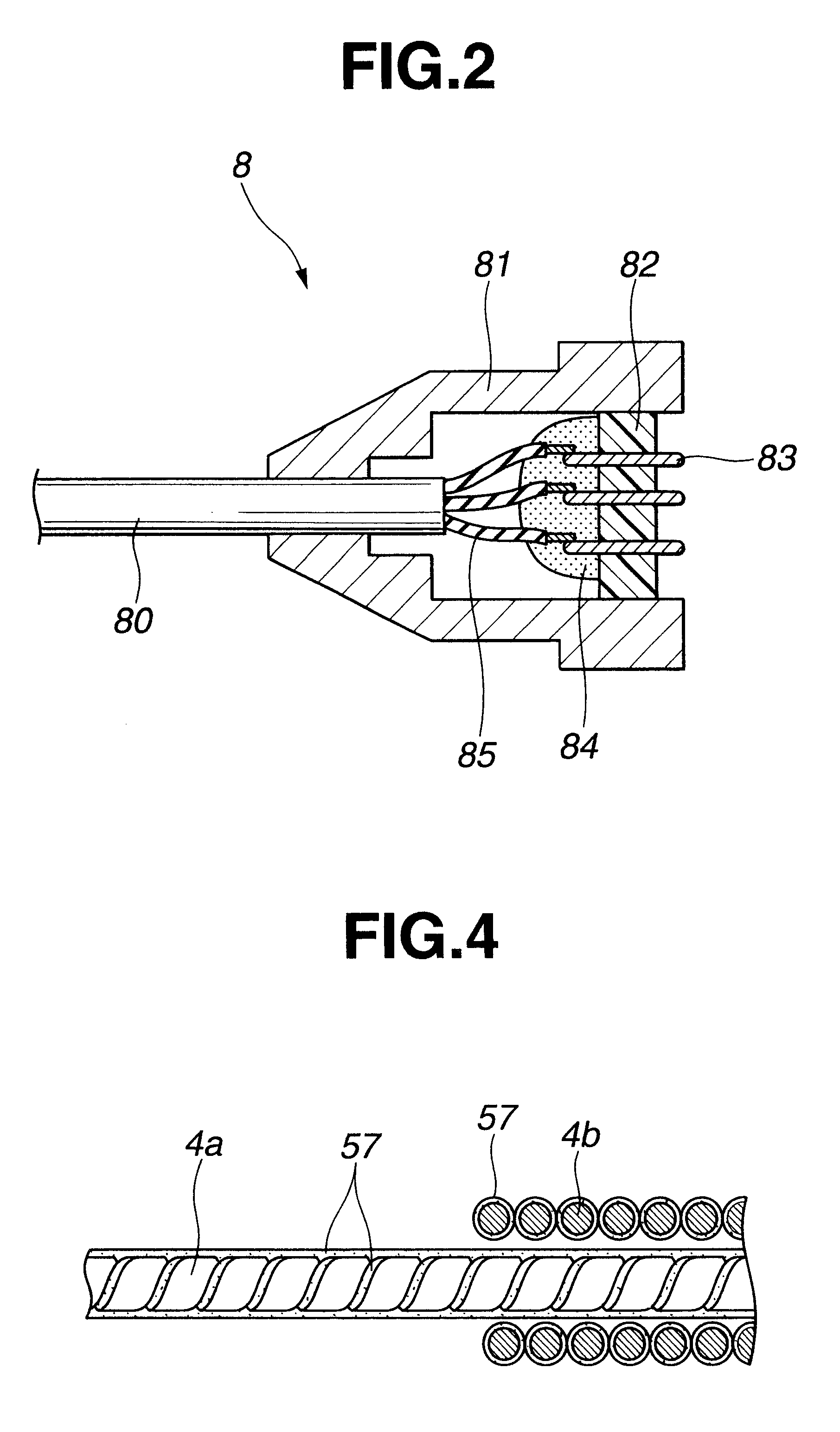
This creates a possibility that the angle wire rusts as the steam remains in the gap between the element wires.
However, the coating has not been carried out steadily in the gap between the element wires and in the part not contacting with other parts, so that it could not prevent rust across the whole wire.
Further, de-flick coat, which is coating containing molybdenum disulfide, which has been used as a coating material in general for a long time, is not only unable to coat the gap between the element wires, but also is deteriorated and peeled off by the high-temperature and high-pressure steam of autoclave sterilization.
Therefore, the de-flick coat did not function as a rust preventive coating at all.

Method used


Image

  • Endoscope having resistance to high-temperature and high-pressure steam
  • Endoscope having resistance to high-temperature and high-pressure steam
  • Endoscope having resistance to high-temperature and high-pressure steam

Examples


first embodiment

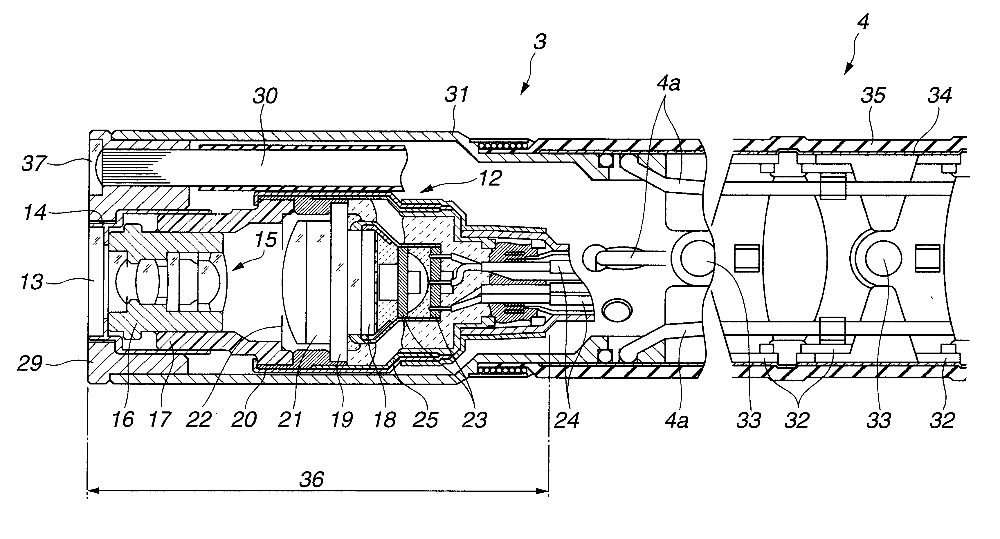
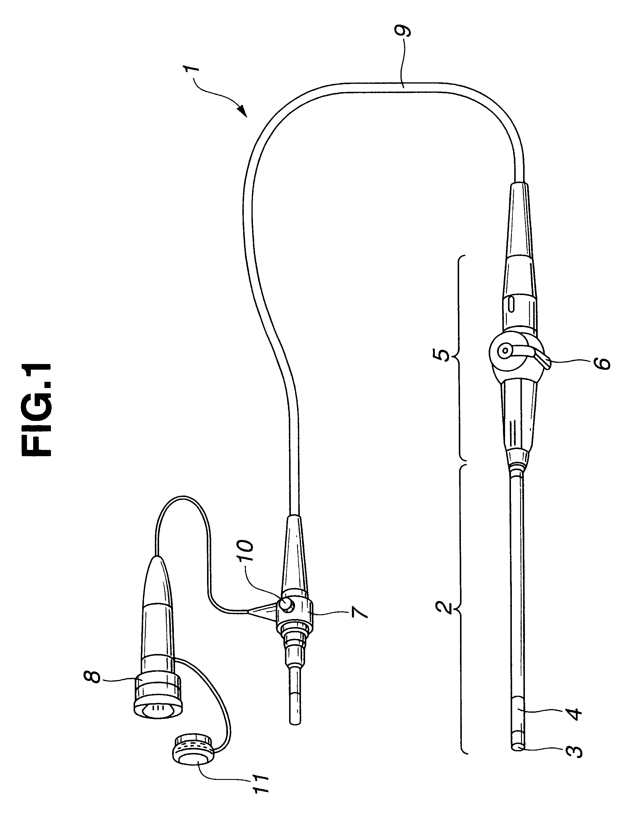
the invention will be explained below with reference to FIGS. 1 through 13.

As shown in FIG. 1, and endoscope has a soft insert section 2, which is to be inserted into a body, at the front-end part of the main body of the endoscope 1. The insert section 2 comprises a front-end section 3 and a bend section 4. There is also provided a control section 5 at the basal end portion of the insert section 2. The control section 5 comprises an angle lever 6 for remotely controlling the bend section 4.

The endoscope 1 also comprises a connector 7, for connecting the endoscope 1 to a light source unit (not shown), and a CCU connector 8, for connecting the endoscope 1 to a video system center. The connector 7, the CCU connector 8 and the control section 5 are connected via a flexible cord 9.

The connector 7 is provided with a switch valve 10 which communicates with the internal space of the endoscope 1 and can be opened and closed by an adapter (not shown). The switch valve 10 has a check valve str...

second embodiment

the invention will be explained below with reference to FIGS. 14 and 15.

FIG. 14 shows a structural example of a image pickup unit 40 having no insulating frame.

The image pickup unit 40 comprises a solid image pickup device 41, a substrate 42 on which electronic parts are mounted, a cable 43 electrically connected to the solid image pickup device 41 via the substrate 42, an objective lens group 44 disposed in front of the solid image pickup device 41, a lens frame 45 to which the objective lens group 44 is assembled, a lens frame supporting frame 46, which is a metallic optical unit supporting frame for holding the lens frame 45 by positioning in the direction of optical axis, a sapphire cover glass 47 disposed in front of the objective lens group 44, and a metallic front-end cover frame 48 hermetically joining the cover glass 47.

The cover glass 47 is hermetically joined with the metallic front-end cover frame 48 by means of brazing or soldering, thus composing a front-end hermetic o...

third embodiment

the invention will be explained below with reference to FIGS. 16 through 18.

According to the present embodiment, an optical window of a front-end hermetic optical covering member 70 is formed of a concave lens 71 which is made of sapphire or a high-heat resistant and high-steam resistant optical member. The structure other than that is similar to the second embodiment. The same members are denoted by the same reference numerals and an explanation thereof will be omitted here.

According to the assembly method of the endoscope of the present embodiment, a lens frame 73, in which the objective lens group 72, except the concave lens 71, which is the optical window, is assembled, is moved in the direction of the optical axis within the lens frame supporting frame 46 to control the focus. Then, the lens frame 73 is adhered and fixed to the lens frame supporting frame 46 at the position where the objective lens group 72 is in focus. The above-mentioned focus control work may be carried out ...


PUM


Abstract

An endoscope having resistance to high-temperature and high-pressure steam including an optical unit having at least one optical member; and optical unit supporting frame for supporting the optical unit so that its position can be adjusted in the direction of the optical axis; and a hermetic optical covering member joined to the optical unit supporting frame and having an optical window for covering at least an end portion of the optical unit when it is joined.

Description

This application claims the benefit of Japanese Application Nos. Hei. 11-199289, filed in Japan, on Jul. 13, 1999, Hei. 11-222856, filed in Japan, on Aug. 5, 1999, Hei. 11-224524, filed in Japan, on Aug. 6, 1999, 2000-172344, filed in Japan, on Jun. 8, 2000, the contents of which are incorporated herein.1. Field of the InventionThe present invention relates to an endoscope which is characterized in the structure of contents disposed in a space within the endoscope and which accommodates to autoclave sterilization.2. Related Art StatementAn endoscope which allows an operator to observe deep inside of a body cavity by inserting an insert section thereof and to carry out remedial operations by using operation tools as necessary has come to be widely used lately.In case of a medical endoscope, it is essential to sterilize and disinfect the endoscope following use to prevent infectious diseases and the like. Hitherto, surgeons have achieved this disinfecting and sterilization process wit...

Claims


Application Information

Patent Timeline
Patent Type & Authority Patents(United States)
IPC IPC(8): A61B1/05
CPCA61B1/00096A61B1/0011A61B1/05A61B1/00101
Inventor HIGUMA, MASAKAZUFUTATSUGI, YASUYUKIAONO, SUSUMU
Owner OLYMPUS CORP
Learn More