Slab foundation construction fixture, particularly as adapts standard girts for pre-use as foundation forms

a technology for building fixtures and foundations, which is applied in the direction of foundation engineering, building repairs, auxiliary members of forms/shuttering/falseworks, etc., can solve the problems of limited commercial success of contemporary proprietary systems which form concrete-slab-on grades, inflexible, and high cost of proprietary systems

Inactive Publication Date: 2003-04-22
BUTLER MICHAEL G
View PDF15 Cites 49 Cited by
  • Summary
  • Abstract
  • Description
  • Claims
  • Application Information

AI Technical Summary

Problems solved by technology

While much prior art can be found in the field of slab foundations and related concrete work, the commercial success of contemporary proprietary systems which form a concrete-slab-on grade is limited.
The primary reasons for this are that the proprietary systems tend to be expensive, contrived, and inflexible.
Furthermore, forming a concrete slab on a prepared building pad is not a significant engineering feat, and so is generally endeavored with simple boards and stakes.
The board and stake concept offers design flexibility, but it does have significant drawbacks.
These drawbacks include: wasted labor to define and check geometry, poor accuracy of surfaces and embedded hardware, difficulty in adjusting form locations after stakes are set, and inconsistent repeatability for multiple units.
Back injury, caused by pulling a conventional stake out of the ground, is a common complaint in the foundation business.
Poor foundation accuracy is always a concern, and it has a more consequential negative affect on the framing process for a structure of light gage metal members.
For a long run of perimeter form this results in frequent potential segmental kinks.
Conforming to custom dimension and design requires the cutting up of relatively expensive lengths of form.
Each supporting assemblage is subject to unwanted lateral movement due to the fact that the each of the supporting stake pairs are required to

Method used


Image

  • Slab foundation construction fixture, particularly as adapts standard girts for pre-use as foundation forms
  • Slab foundation construction fixture, particularly as adapts standard girts for pre-use as foundation forms
  • Slab foundation construction fixture, particularly as adapts standard girts for pre-use as foundation forms

Examples


Embodiment Construction

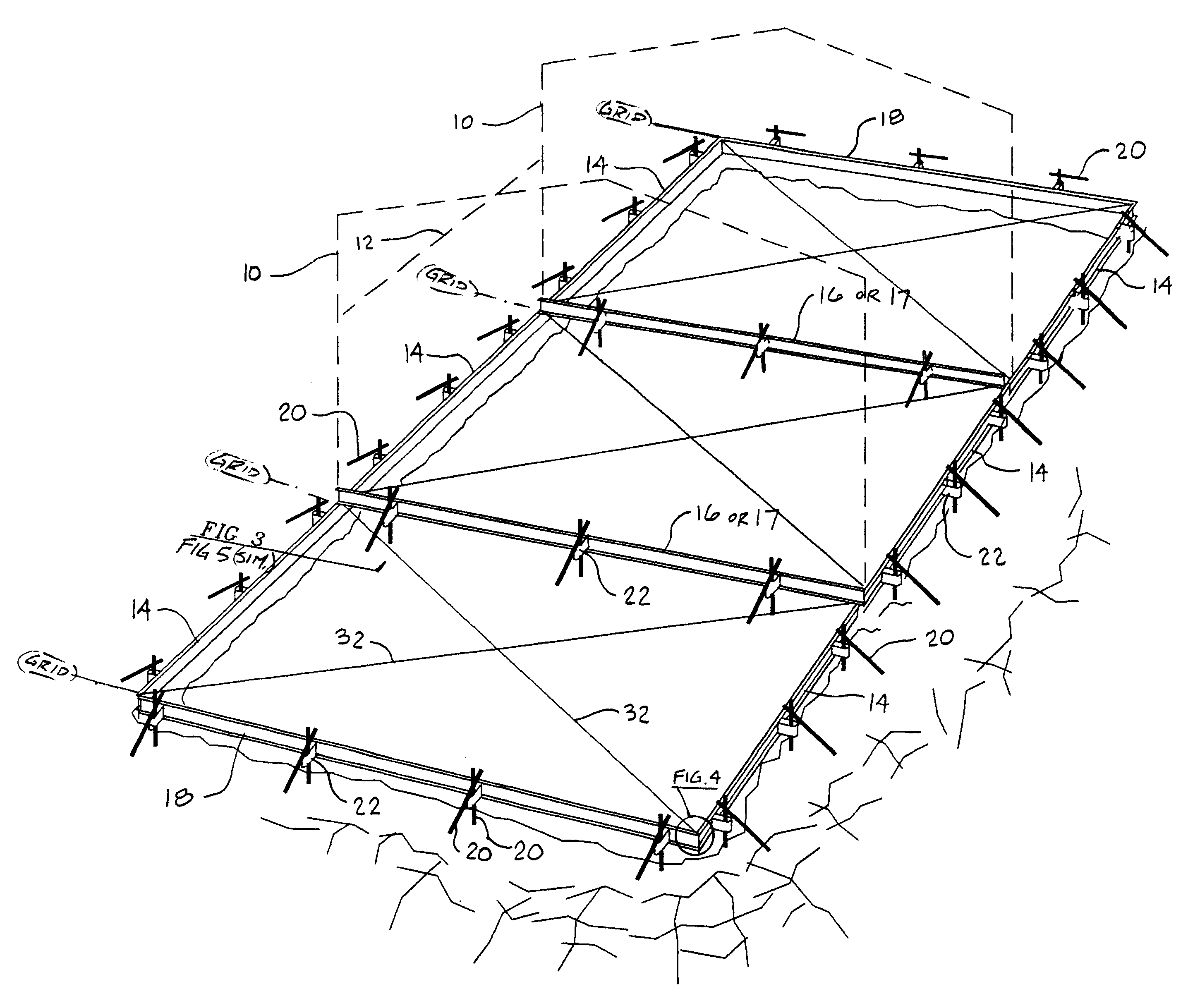
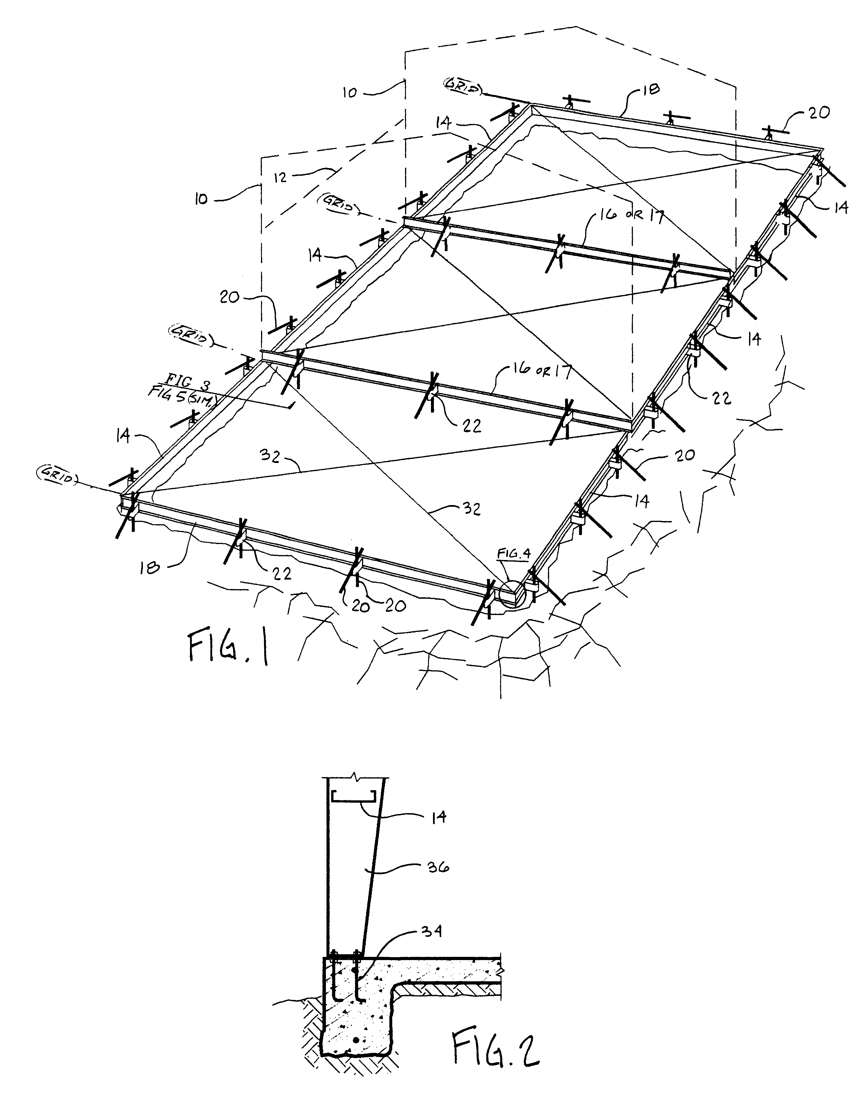
Beginning in the drawings, FIG. 1 shows a view of a form-set as was disclosed in this inventor's patent application Ser. No. 08 / 600,408, filed on Feb. 12, 1996 for CONCRETE SLAB FOUNDATION FORMING DEVICES. The difference in this particular form-set is that the forming members, as is, are subsequently utilized as wall girts between structural frames.

An example of the outline of a building frame 10 is shown to make clear this relationship, as a form / girt 14 is identical to the future wall girt located by a dashed line 12. The selfsame identical connections to form / girt 14 as are later used in the wall are also used in first deploying form / girt 14 as a form. The building outline is generally identical at its end walls, or end frames 1 as the case may be, as is illustrated in FIG. 1 on two interior grid lines.

A form 18 is parallel to the structural frames. Form 18 can subsequently be an end wall girt, or it can be longitudinal wall girt, commonly with length modification, or it can simp...


PUM


Abstract

A system for forming concrete slabs has been developed for commercial buildings having a steel moment-frame structure. This system utilizes the cold-formed-steel framing members, such as the wall girts shipped with a particular building package, to be first utilized as slab foundation forming elements before being framed into the building. The system defines foundation geometry upon simple assembly of the forming elements, and efficiently provides for placement of anchoring hardware which corresponds exactly to the connections of the structural frames.

Description

1. Field of the InventionThe present invention generally concerns the forming of concrete slabs with a light-gage-steel form-set that defines a given geometry upon assembly.The present invention particularly concerns a form set made up, as much as possible, from girt members that are normally, and will normally be, used in the construction of the building atop a concrete slab foundation.The present invention further particularly concerns hardware that interconnects foundation form members while also fixing the locations of foundation anchor bolt elements in a manner exactly corresponding to connections of the structural frames of the building.2. Description of the Prior ArtWhile much prior art can be found in the field of slab foundations and related concrete work, the commercial success of contemporary proprietary systems which form a concrete-slab-on grade is limited. The primary reasons for this are that the proprietary systems tend to be expensive, contrived, and inflexible. Fur...

Claims


Application Information

Patent Timeline
IPC IPC(8): E04G13/00E02D27/00E02D27/02E04B5/10E04B5/14
CPCE02D27/00E02D27/02E04G13/00E04B5/10E02D2220/00
Inventor BUTLER, MICHAEL G.
Owner BUTLER MICHAEL G
Why Eureka
Try Eureka