Cleaning device

Inactive Publication Date: 2003-04-29
DISA IND
View PDF18 Cites 5 Cited by
  • Summary
  • Abstract
  • Description
  • Claims
  • Application Information

AI Technical Summary

Problems solved by technology

This increase of the flow resistance causes a pressure loss of the fluid flow when passing through the filter element which, in turn, impairs the discharge of the cleaned fluid or makes it possible only by means of an expensive and high-energy additional suction device.
However, it was found that filter elements cleaned in this way again generate a high-pressure drop of the fluid flow to be cleaned already after a comparatively short operating period.
Even though with the described measures an improvement of the cleaning action of the cleaning fluid can be obtained, it was found that even the introduction of the cleaning fluid into the interior of the filter element in the form of individual pressure pulses and/or by means of a suitable introduction nozzles

Method used


Image

  • Cleaning device
  • Cleaning device

Examples


Embodiment Construction

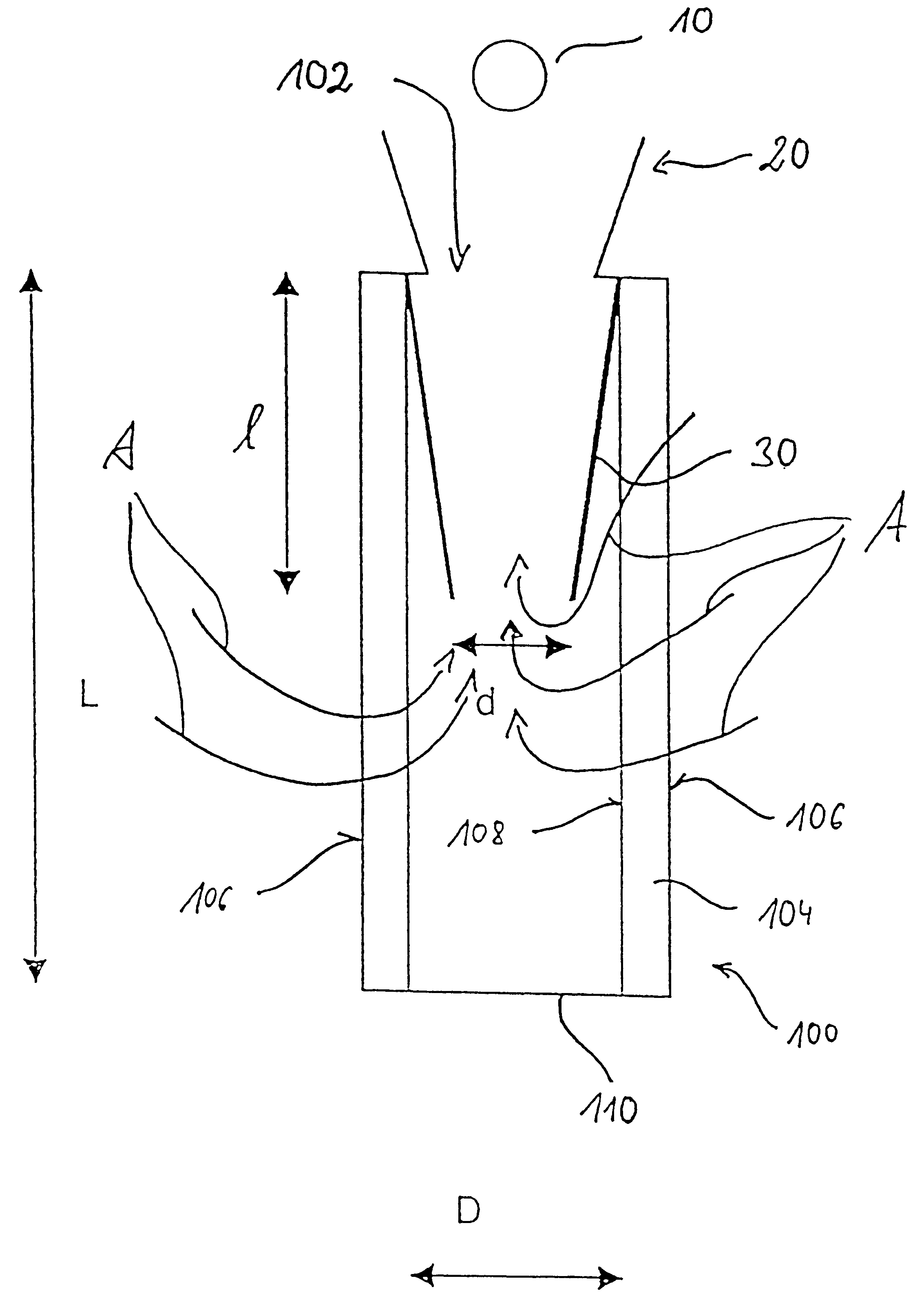
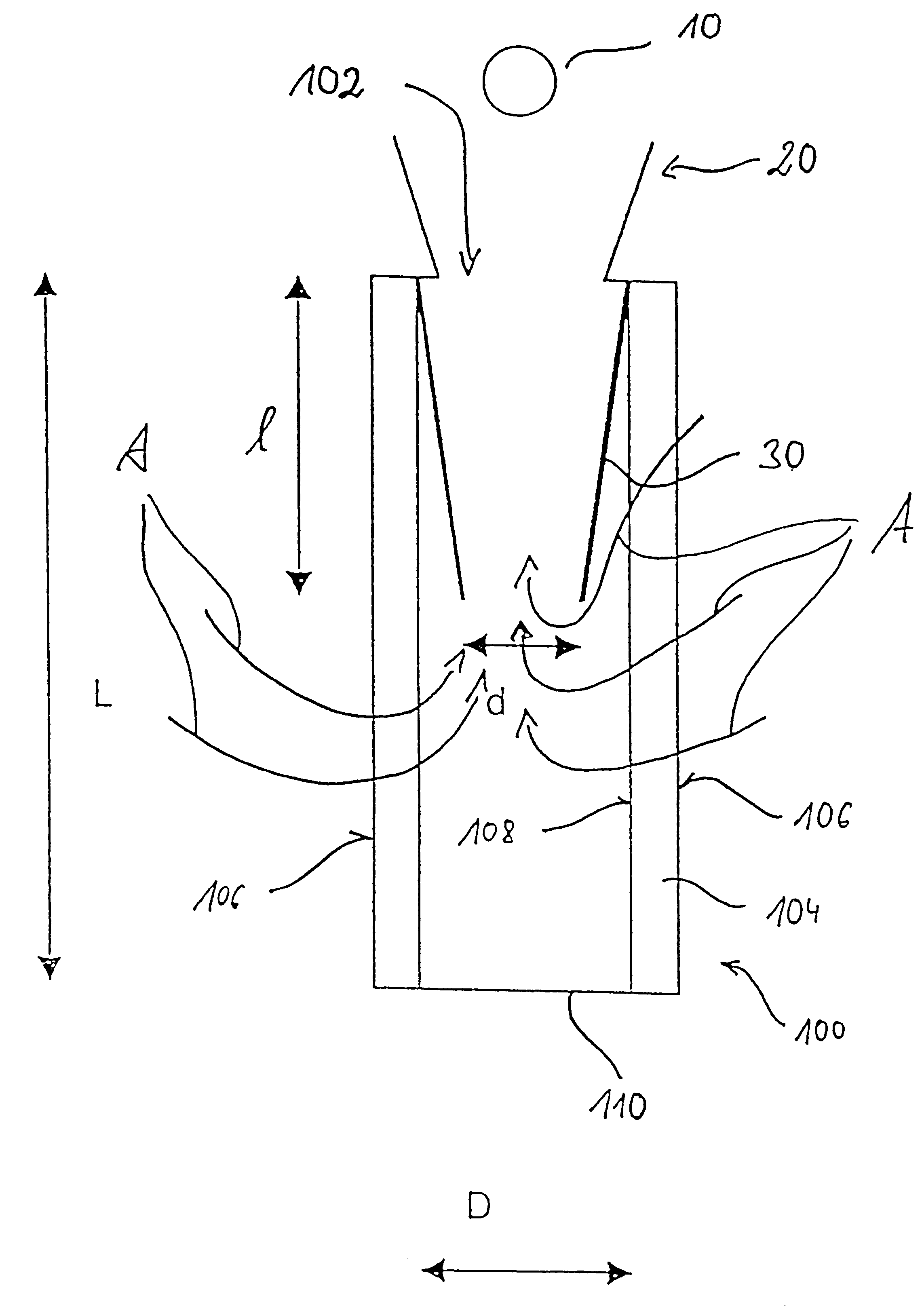
The cleaning device illustrated in the drawing is comprised substantially of a line system 10, such as a compressed air line and having a discharge opening for the cleaning fluid; a nozzle 20 through which the cleaning fluid, such as compressed air, can be discharged into the interior of a filter element which in its entirety is referenced by 100; and a distribution element 30 inserted into an opening 102 of the filter element forming during the filtration operation of the filter element 100 a discharge for the cleaned fluid.

The filter element 100 to be cleaned with the cleaning device illustrated in the drawing has substantially the shape of a hollow cylinder wherein the outlet opening 102 is arranged at one axial end of the filter element while the cylinder mantle surface 106 is formed by a filter material 104 such as, for example, a filter membrane or a filter fleece. At the end opposite the outlet opening the filter element 100 is closed off by a bottom 110.

During normal filtrat...


PUM

PropertyMeasurementUnit
Fractionaaaaaaaaaa
Fractionaaaaaaaaaa
Fractionaaaaaaaaaa

Abstract

The invention relates to a device for cleaning the filter surface of a filter element, through which the liquid to be filtered flows, during a filtration operation using a pressurised cleaning fluid. According to an improvement of the invention, a distribution device is provided which delivers an essentially even pressure distribution of the cleaning fluid over the entire area of the filter surface to be cleaned.

Description

1. Field of the InventionThe invention relates to a device for cleaning a filter surface of a filter element, through which liquid to be filtered flows during a filtration operation, by means of a pressurized cleaning fluid.2. Description of the Related ArtSuch devices are, for example, required for cleaning dust filters used in industrial facilities. The dust filters used for industrial purposes are in many cases approximately in the form of a hollow cylinder wherein at one end of the filter elements an outlet opening for the cleaned fluid such as, for example, flue gas from which dust has been removed, is provided while a cylinder mantle surface of the filter element is formed by a filter substance such as a filter membrane or a filter fleece. This mantle surface of the filter element then forms the filter surface through which during the filtration operation the fluid to be cleaned, such as flue gas, flows, wherein the dust particles contained in the flue gas are retained by the ...

Claims


Application Information

Patent Timeline
IPC IPC(8): B01D46/24B01D46/00B01D46/04
CPCB01D46/24B01D46/0068B01D46/71B01D46/04
Inventor BIHLET, KLAUSBISHOP, ANGUS J.
Owner DISA IND
Why Eureka
Try Eureka