Pulsed source scanning interferometer

a scanning interferometer and pulse source technology, applied in the field of scanning interferometers, can solve the problems of mechanical undesirable shift-and-hold motion of the stepping method, slowing down the data acquisition process, and no longer being generally preferred in the industry, and achieve the effect of improving signal utilization

Inactive Publication Date: 2003-04-29
BRUKER NANO INC
View PDF2 Cites 209 Cited by
  • Summary
  • Abstract
  • Description
  • Claims
  • Application Information

AI Technical Summary

Benefits of technology

The pulse length and the scanning velocity are selected such that a minimal change in OPD occurs during the pulse. As long as the duration of the pulse is shorter than the detector's integration time, the effective integration time and the corresponding phase shift a...

Problems solved by technology

In practice, the shift-and-hold motion of the stepping method is mechanically undesirable because a finite amount of time is required for the shifted portion of the apparatus to settle into a static condition, thereby slowing down the process of data acquisition.
Therefore, this method is no longer generally preferred in the industry.
On the other hand, this approach has the disadvantage of continuously varying the OPD, which, in conjunction with the...

Method used


Image

  • Pulsed source scanning interferometer
  • Pulsed source scanning interferometer
  • Pulsed source scanning interferometer

Examples


Embodiment Construction

The present invention consists of a single inventive concept, the realization that the signal loss resulting from the finite integration time of light detectors can be minimized by utilizing a pulsed light source of sufficient intensity to produce a significantly detectable signal on the detector's surface. By using a sufficiently short pulse length and synchronizing the source and the integration time of the detector, an effectively instantaneous integration time can be achieved, during which a negligible phase shift occurs and a correspondingly negligible loss of signal is experienced. As used herein, "synchrony" between the pulsed emission of radiation and the detector's integration time is intended to mean a condition whereby at least a portion of the pulsed wavefront is received by the detector while it is integrating the incident signal. Such condition is also referred to as one of "contemporaneous" light-intensity measurement of the pulsed signals.

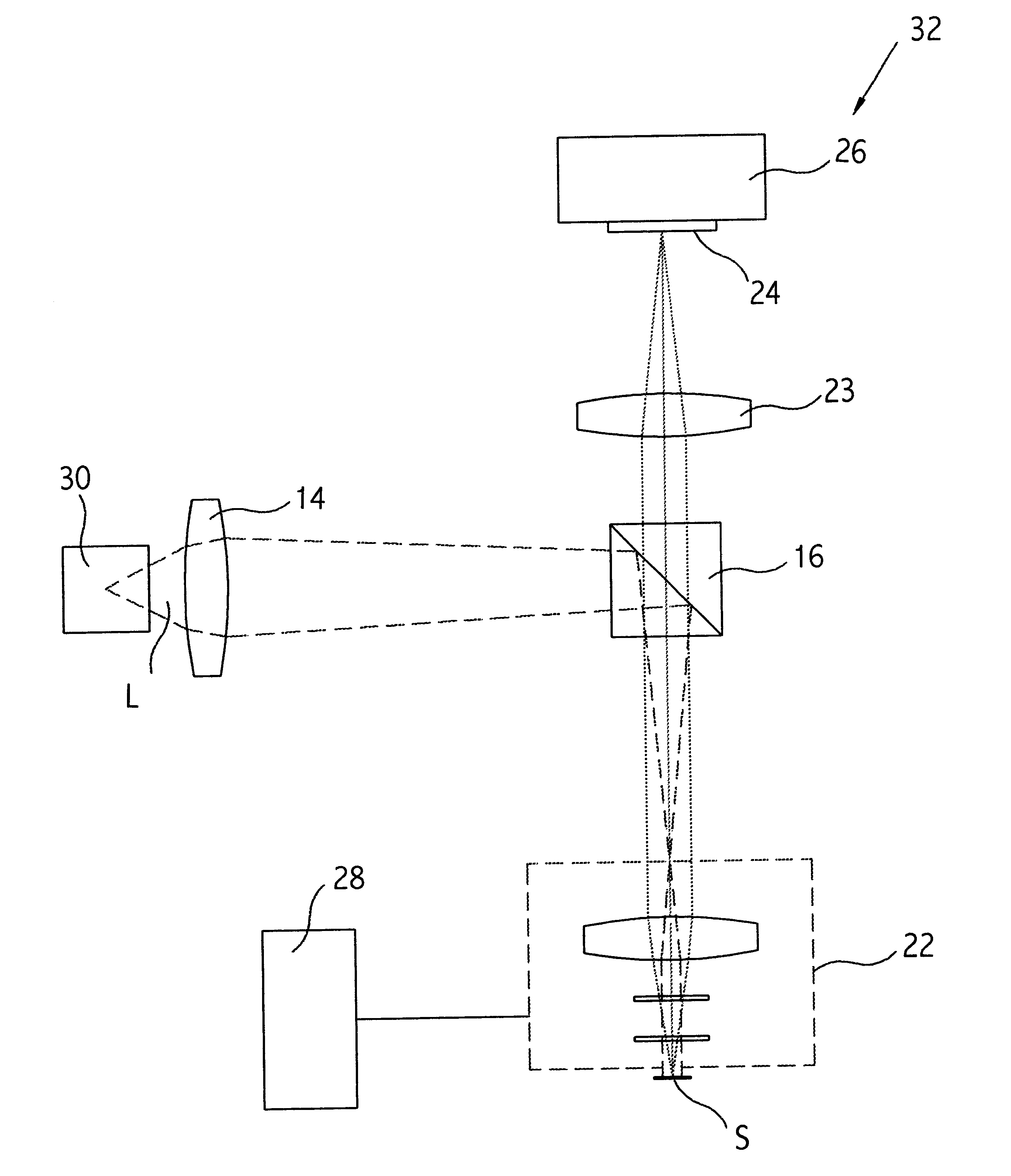
Referring to the drawings, w...


PUM


Abstract

A pulsed light source in used conjunction with a ramping scanning mechanism for phase-shift and vertical-scanning interferometry. The pulse length and the scanning velocity are selected such that a minimal change in OPD occurs during the pulse. As long as the duration of the pulse is shorter than the detector's integration time, the effective integration time and the corresponding phase shift are determined by the length of the pulse, rather than the detector's characteristics. The resulting minimal phase shift produces negligible loss of fringe modulation, thereby greatly improving signal utilization during phase-shifting and vertical-scanning interferometry.

Description

1. Field of the InventionThis invention is related in general to the field of scanning interferometry and, in particular, to an improved approach for signal acquisition by utilizing a pulsed light source.2. Description of the Related ArtAs well understood in the art of phase shifting and vertical scanning interferometry, the optical path difference (OPD) between a test beam and a reference beam is varied in order to make a measurement. This is typically accomplished by shifting either the test surface or the reference surface of the interferometer axially by a predetermined distance during or between times of acquisition of data frames. The shift is normally carried out in steps or by continuous motion at a known, ideally constant, speed.In the stepping method, the sample surface (or, alternatively, the reference surface) is moved between data frames and held still during data acquisition; thus, the OPD is kept constant during acquisition of each data frame. In practice, the shift-a...

Claims


Application Information

Patent Timeline
IPC IPC(8): G01B9/02
CPCG01B9/02057G01B9/02069G01B9/02014G01B9/0209
Inventor AZIZ, DAVID J.KNOWLDEN, ROBERT E.ABBENE, MATTHEW P.
Owner BRUKER NANO INC
Why Eureka
Try Eureka