Time division switch with inserter and dropper using external memory and time division switching method

a time division switch and dropper technology, applied in the field of time division switch and time division switch, can solve the problems of increasing the scale of the system, avoiding the system being discretized, and exhibiting a large scal

Inactive Publication Date: 2003-04-29
NEC CORP
View PDF13 Cites 2 Cited by
  • Summary
  • Abstract
  • Description
  • Claims
  • Application Information

AI Technical Summary

Benefits of technology

It is an object of the present invention to provide a time-division switching method which allows a time-division switch to have several functions which are conventionally achieved by different apparatus for exclusive use.
It is another object of the present invention to provide a time-division switch which achieves several functions which are conventionally achieved by different apparatus for exclusive use.
With the time-division switching method and the time-division switch, three address factor storage areas for a head address, an end address and an address count are provided for each time slot, and circulating designation of address is possible for each time slot. Consequently, the time-division switch can perform supervision or sending out of a multi-frame signal for all time slots and can also perform an ordinary switching function. Accordingly, not only communication of audio data, but also transfer of data having a nature of a multi-frame signal train as specified in the PIAFS can be performed collectively by a single LSI without using an external apparatus for exclusive use. Consequently, the time-division switch can perform communication of both of data and an audio signal and can be implemented in such a small size and low power consumption that it can be well applied to a system construction for mobile computing and so forth.

Problems solved by technology

Consequently, it cannot be avoided that the system is discretized and exhibits a large scale.
Further, as the number of lines increases, also the numbers of required apparatus for exclusive use increase, which increases the scale of the system.

Method used


Image

  • Time division switch with inserter and dropper using external memory and time division switching method
  • Time division switch with inserter and dropper using external memory and time division switching method
  • Time division switch with inserter and dropper using external memory and time division switching method

Examples


Embodiment Construction

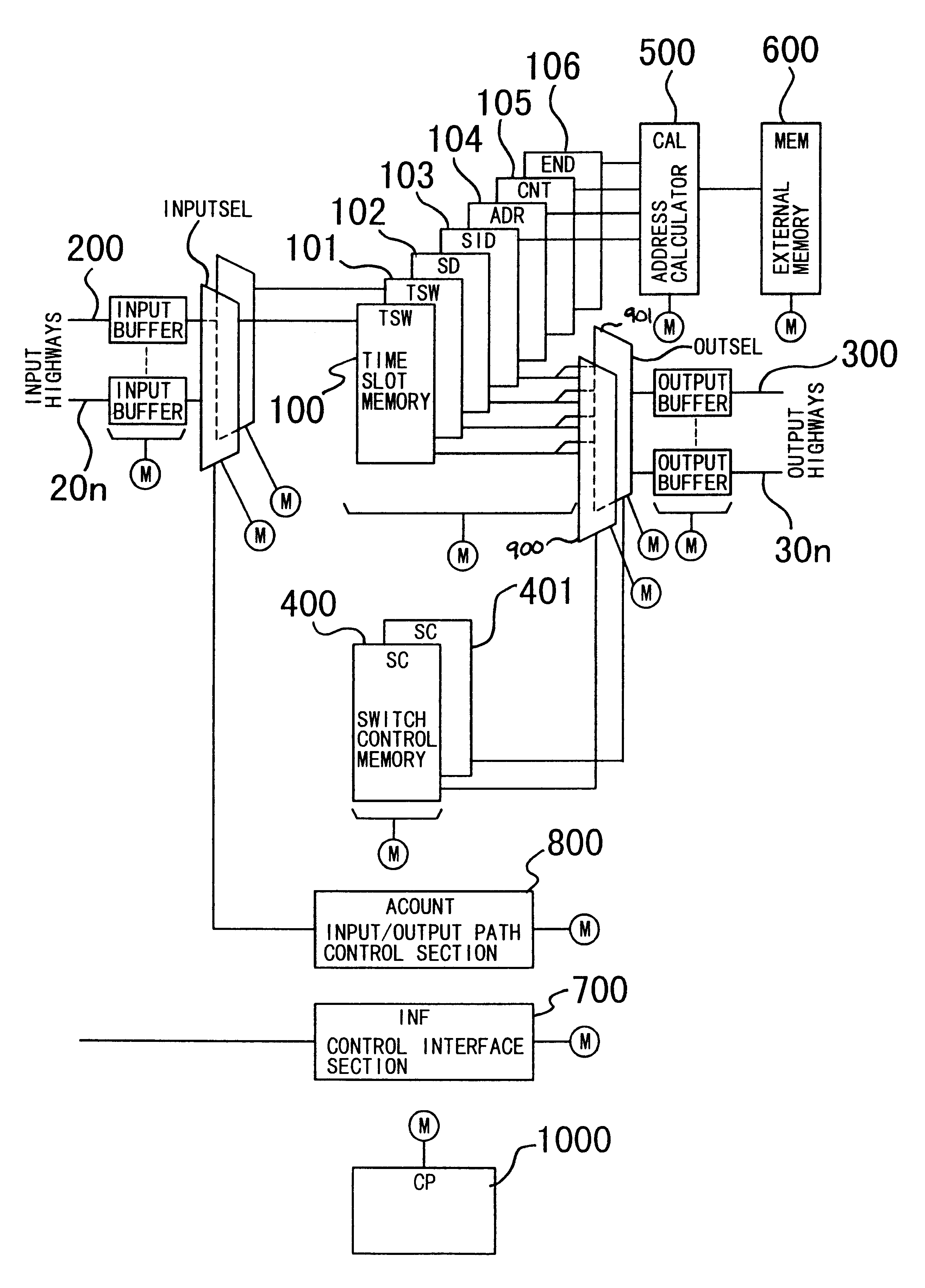
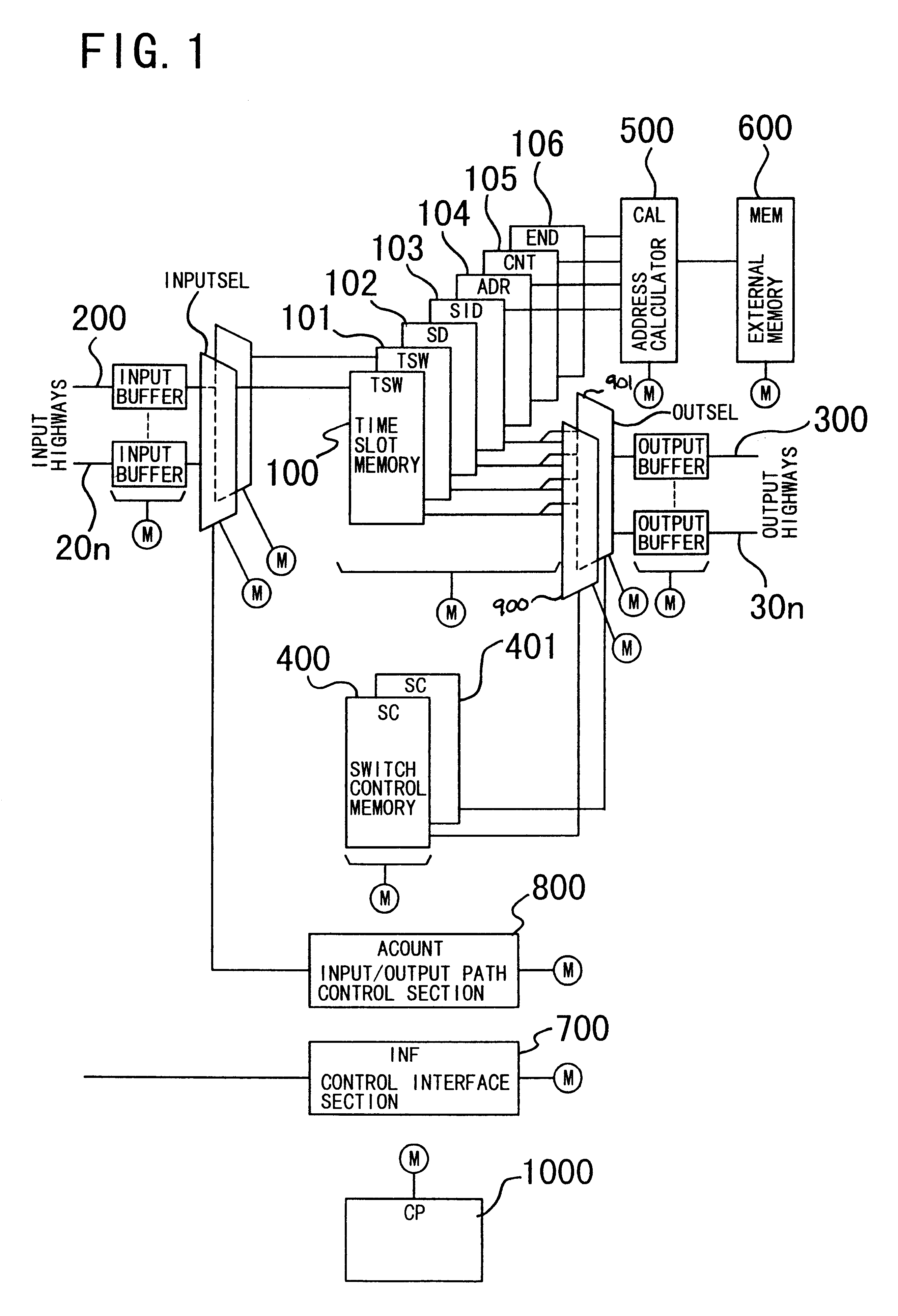
Referring first to FIG. 1, there is shown a time-division switch with an inserter and a dropper of the external memory added type. The time-division switch shown includes time slot memories (TSW) 100 and 101 each for temporarily storing time slots on a highway for each time slot, external data storage memory (SD) 102 for storing data read out from an external memory (MEM) 600, switch control memories (SC0) 400 and 401 for storing designation bits for designating n input highways 200 to 20n and time slots of them and n output highways 300 to 30n and time slots of them, respectively, a setting data memory (SID) 103 for producing fixed data on an arbitrary time slot, a head address memory (ADR) 104, an end address memory (END) 106 and an address counter memory (CNT) 105 for controlling the external memory 600, an address calculator (CAL) 500 for referring to the head address memory (ADR) 104, end address memory (END) 106 and address counter memory (CNT) 105 to calculate an address, a c...


PUM


Abstract

The invention provides a time-division switch and a time-division switching method by which a multi-frame signal of an arbitrary bit length can be outputted to or inputted from an arbitrary time slot. The time-division switching method is applied to weitchably connect time slots between different highways in time-division multiplex communication. The switch includes an external memory to which data from input time slots may be dropped, and from which data may be inserted into output time slots. Fixed data such as tone data may also be inserted into time slots. Dropping and insertion may be performed to replace existing time slot data or to fill new time slots.

Description

BACKGROUND OF THE INVENTION1. Field of the InventionThe present invention relates to a time-division switch and a time-division switching method for a time-division switch.2. Description of the Related ArtConventionally, a time-division switch merely has a basic function to arrange time slots of a data highway inputted thereto arbitrarily on time slots on another highway to be outputted to interconnect different apparatus, which are physically connected to each other outside the time-division switch, with such time slots so that data or an audio signal may be communicated between the different apparatus.Meanwhile, such functions as sending out a tone signal of a busy-back tone, or the like or sending out or receiving a multi-frame signal must all rely upon externally connected apparatus for exclusive use.Consequently, it cannot be avoided that the system is discretized and exhibits a large scale.As described above, a conventional time-division switch requires use of external apparat...

Claims


Application Information

Patent Timeline
Patent Type & Authority Patents(United States)
IPC IPC(8): H04J3/08H04Q11/08H04J3/00H04Q11/04
CPCH04J3/08H04Q11/08H04Q2213/13097H04Q2213/13103H04Q2213/13393H04Q2213/13178H04Q2213/13213H04Q2213/13216H04Q2213/13174
Inventor IKEDA, SABUROU
Owner NEC CORP
Why Eureka
Try Eureka