Method and system for reducing non-linearities

a nonlinearity and nonlinearity technology, applied in the field of signal generation, can solve the problems of cost and the need for precise balance between reference, modulator errors are not typically corrected, and amplifier modifications to reduce nonlinear distortion

Inactive Publication Date: 2003-05-20
KEYSIGHT TECH
View PDF5 Cites 42 Cited by
  • Summary
  • Abstract
  • Description
  • Claims
  • Application Information

AI Technical Summary

Benefits of technology

In an embodiment of the present invention, a method of reducing non-linearities of a circuit includes providing and pre-distorting an input signal. The input signal includes a constant component and a time-varying component. The pre-distorted input signal is input to the circuit and an output signal is obtained from the circuit. A carrier signal is subtracted from the output signal, thereby yielding an error signal. An error signal envelope is determined and is demodulated using a demodulating signal related to the input signal. The parameters of the pre-distorted input signal are adjusted with reference to the demodulated converted error signal, thereby causing an amplitude of the error signal envelope to approach a constant value.
In another embodiment of the present invention, a system for reducing non-linearities includes an input-signal-generation circuit and a carrier-signal-generation circuit. The signal-generation circuit is adapted to generate an input signal having a constant component and a time-varying component. The carrier-signal-generation circuit is adapted to generate a carrier signal. The circuit includes an input connected to the input-signal-generation circuit and adapted to receive the input signal and a modulator connected to the carrier-signal-generation circuit and adapted to modulate the input signal with the carrier signal. The circuit also includes an amplifier, connected to the modulator, adapted to amplify the modulated input signal. An output is connected to the amplifier and is adapted to output the modulated amplified input signal. The system includes a pre-distorter that is adapted to adjust signal parameters. The pre-distorter is connected to the circuit. There is also a measurement circuit connected to the carrier-signal-generation circuit and to the output. The measurement circuit is adapted to yield an envelope of an error signal. The envelope comprises a function of an imbalance of the measurement circuit. Pre-distortion parameter adjustments are used to cause an amplitude of an envelope of the error signal to approach a constant value, thereby reducing non-linearities of the circuit.

Problems solved by technology

In general, feedback loop delays tend to limit the available signal bandwidth and can lead to instability if bandwidth restrictions are exceeded.
Modulator errors are not typically corrected using feedforward linearization.
Feedforward linearization performance is typically limited by the quality of a second, reference amplifier, used to amplify the measured distortion.
Disadvantages of using feedforward compensation include expense and the need for precise balances between reference and signal paths in order to obtain acceptable performance.
Inaccurate measurements of the gain variations can bias the parameter estimation, thereby impairing the performance of pre-distortion linearization.
An inherent problem with adaptive approaches to linearization is that the system being linearized cannot distinguish distortion induced by non-linearities of, for example, the modulator or the PA within the signal path from non-linearities induced by measurement components used to measure the non-linearities within the signal path.
These ultra-linear measurements are often prohibitively expensive.
From the foregoing it can be seen that non-linearities of signal-generation circuits have required ultra-linear measurement components, which are often prohibitively expensive.
A carrier signal is subtracted from the output signal, thereby yielding an error signal.

Method used


Image

  • Method and system for reducing non-linearities
  • Method and system for reducing non-linearities
  • Method and system for reducing non-linearities

Examples


Embodiment Construction

In the following Detailed Description, specific details are set forth in order to provide a thorough understanding of embodiments of the present invention. However, it will be apparent to those of ordinary skill in the art that the present invention can be practiced in other embodiments that depart from these specific details. In other instances, detailed descriptions of well-known methods, devices, logical code (e.g., hardware, software, firmware), and the like are omitted so as not to obscure description of embodiments of the present invention with unnecessary detail. Preferred embodiments of the present invention and its advantages are best understood by referring to FIGS. 1-6 of the Drawings, in which like numerals are used for like and corresponding parts of the various Drawings.

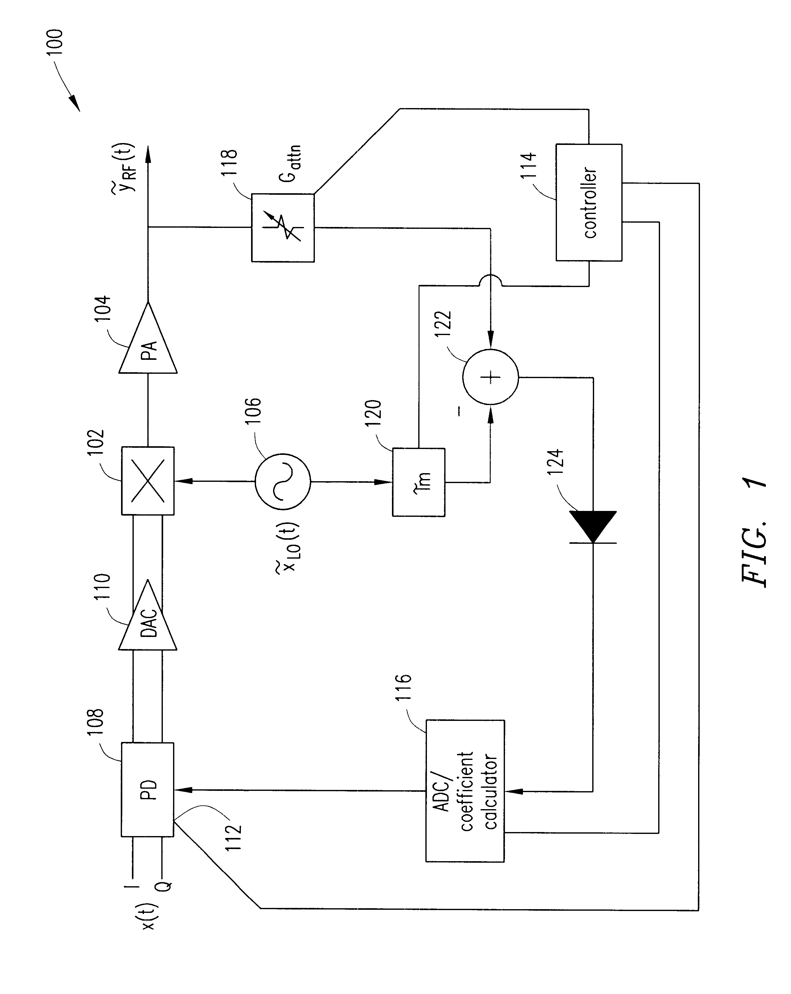
FIG. 1 is a block diagram of a linearization circuit 100 in accordance with teachings of the present invention. The linearization circuit 100, which has a base-band input signal x(t), could be, for exam...


PUM


Abstract

Non-linearities of signal-generation circuits that typically include a series arrangement of a modulator and a power amplifier are reduced by connecting a measurement circuit to an output of the signal-generation circuit and at another point along a signal path of the signal-generation circuit. A predistorted input signal is applied to an input of the signal-generation circuit. The pre-distorted signal includes a constant component and a time-varying component, such that the predistorted input signal excites non-linear modes of the signal-generation circuit. The measurement circuit is balanced so that a portion of the predistorted input signal that passes through the measurement circuit does not include a time-varying component and therefore does not excite non-linearities of the measurement circuit. Adjustments are made to the predistorted input signal in order to reduce non-linearities of the signal-generation circuit.

Description

1. Technical Field of the InventionThe present invention relates in general to the field of signal generation, and in particular, by way of example but not limitation, to reduction of non-linearities in signal-generation circuits. A major objective of the present invention is to reduce non-linearities in signal-generation circuits.2. Description of Related ArtAttempts to improve the linearity of a series combination of a modulator and power amplifier (PA) include: (a) choosing components that are more linear; and (b) using linearization techniques such as, for example, feedback, feedforward, and pre-distortion. Feedback generally refers to feeding back at least a part of a signal to a delayed version of the signal in order to correct the signal substantially in real time. Feedforward generally refers to correcting a signal in advance so the future signals are corrected. Because components that exhibit greater linearity are often more expensive than components that exhibit lesser lin...

Claims


Application Information

Patent Timeline
Patent Type & Authority Patents(United States)
IPC IPC(8): H03F1/32H03C1/06H04B1/04
CPCH03F1/3247
Inventor BRAITHWAITE, RICHARD NEIL
Owner KEYSIGHT TECH
Why Eureka
Try Eureka