Touch panel

a technology of touch panel and display panel, which is applied in the field of touch panel, can solve the problems of increased cost, complicated circuit structure and signal processing, and difficulty in arranging liquid crystal display apparatus (lcd), and achieve the effect of reducing the number of transducers

Inactive Publication Date: 2003-05-20
TOUCH PANEL SYST
View PDF20 Cites 94 Cited by
  • Summary
  • Abstract
  • Description
  • Claims
  • Application Information

AI Technical Summary

Benefits of technology

Such a touch panel utilizes a characteristic that acoustic wave (e.g. surface ultrasonic wave or the like) is propagated straight on the surface of a propagation medium. Specifically, when the acoustic wave turns around the end face of the panel, it spirally travels on the surface having semicircular shape in section. Thus, the acoustic wave generated on the rear surface of the touch panel turns around the end face of the panel and is then guided to the front surface as a touch surface. When the acoustic wave are propagated on the surface of the propagation medium, the traveling direction of the acoustic wave may be easily understood by referring a development view for the propagation medium which is a hollow and made up only of a shell. For example, as shown in FIG. 1, the traveling direction (see the arrow) of the acoustic wave traveling on the spherical surface of a sphere 1 corresponds to the outline of a section made by cutting the sphere along a plane including the center of the sphere 1. As shown in FIG. 2, when acoustic wave travels on the surface of a columnar propagation medium 2, it spirally travels on the surface of the propagation medium as shown by the arrow. Thus, when the end face or corner portion of the propagation medium is chamfered and processed into a gentle surface (curved surface), the acoustic wave are directed from one of the front and rear surfaces of the propagation medium to another surface practically without any loss.
The touch panel (position detecting device) according to the present invention further comprises a pair of X-axis reflecting means 14 and a pair of Y-axis reflecting means 15. That is, the pair of X-axis reflecting means 14 include a first X-axis reflecting means 14a for reflecting the acoustic wave, which is propagated in a X-axis direction from the transmitting transducer 12a in the transmitting area, to a negative (-) Y-axis direction, and a second X-axis reflecting means 14b, formed at the sideward section opposed to the first X-axis reflecting means in the substrate 11, for reflecting the acoustic wave, which is propagated in the -Y-axis direction, to a negative (-) X-axis direction. The pair of Y-axis reflecting means 15 also include a first Y-axis reflecting means 15a for reflecting the acoustic wave, which is propagated in the Y-axis direction from the transmitting transducer 13a, to the -X-axis direction, and a second Y-axis reflecting means 15b, formed at the sideward section opposite to the first Y-axis reflecting means of the substrate 11, for reflecting the acoustic wave, which is propagated in the -X-axis direction, to the -Y-axis direction. In this example, each reflecting means is composed of a reflecting array. These reflecting means allows the acoustic wave to be propagated in the X-axis and the Y-axis directions in the display area (i.e. the area surrounded by the reflecting means).
In this touch panel, no raised portion is practically formed on the front surface of the substrate 11. This enables the touch panel to be enhanced in applicability to thin LCD monitors and to be simplified in structure. In particular, such a touch panel may be simplified in circuit structure and signal processing.
Thus, the acoustic wave which has passed through the first Y-axis reflecting means 15a in the Y-axis direction turns around from the front surface to the rear surface of the substrate 41 through the chamfered portion 46, and is propagated in the -Y-axis direction on the rear surface of the substrate 41. The propagated acoustic wave reaches the slant-chamfered portion 47, and then travels from the rear surface to the front surface with 90 degrees of torsion. Then, it passes through the second X-axis reflecting means 14b in the -X-axis direction on the front surface of the substrate 41, and travels from the front surface to the rear surface with 90 degrees of torsion by the slant-chamfered portion 45. Eventually, it is detected by the X-axis receiving transducer 42b placed in the receiving area. This allows the single receiving transducer 42b to detect both acoustic waves propagated in the X-axis and Y-axis directions.
According to the present invention, the acoustic waves in both X-axis and the Y-axis directions may be converged by use of the chamfered portion, and these acoustic waves may be branched into X-axis and Y-axis directions. Thus, the number of transducers may be reduced.

Problems solved by technology

Using such a signal processing leads to two partially or entirely duplicate groups not only of the switching circuit but also of the transmitting and receiving circuits in the controller, which results in complicated circuit structure and signal processing as well as increased cost.
This makes difficult to arrange a liquid crystal display apparatus (LCD), particularly a thin LCD monitor to the propagation medium.

Method used


Image

  • Touch panel
  • Touch panel
  • Touch panel

Examples


example 1

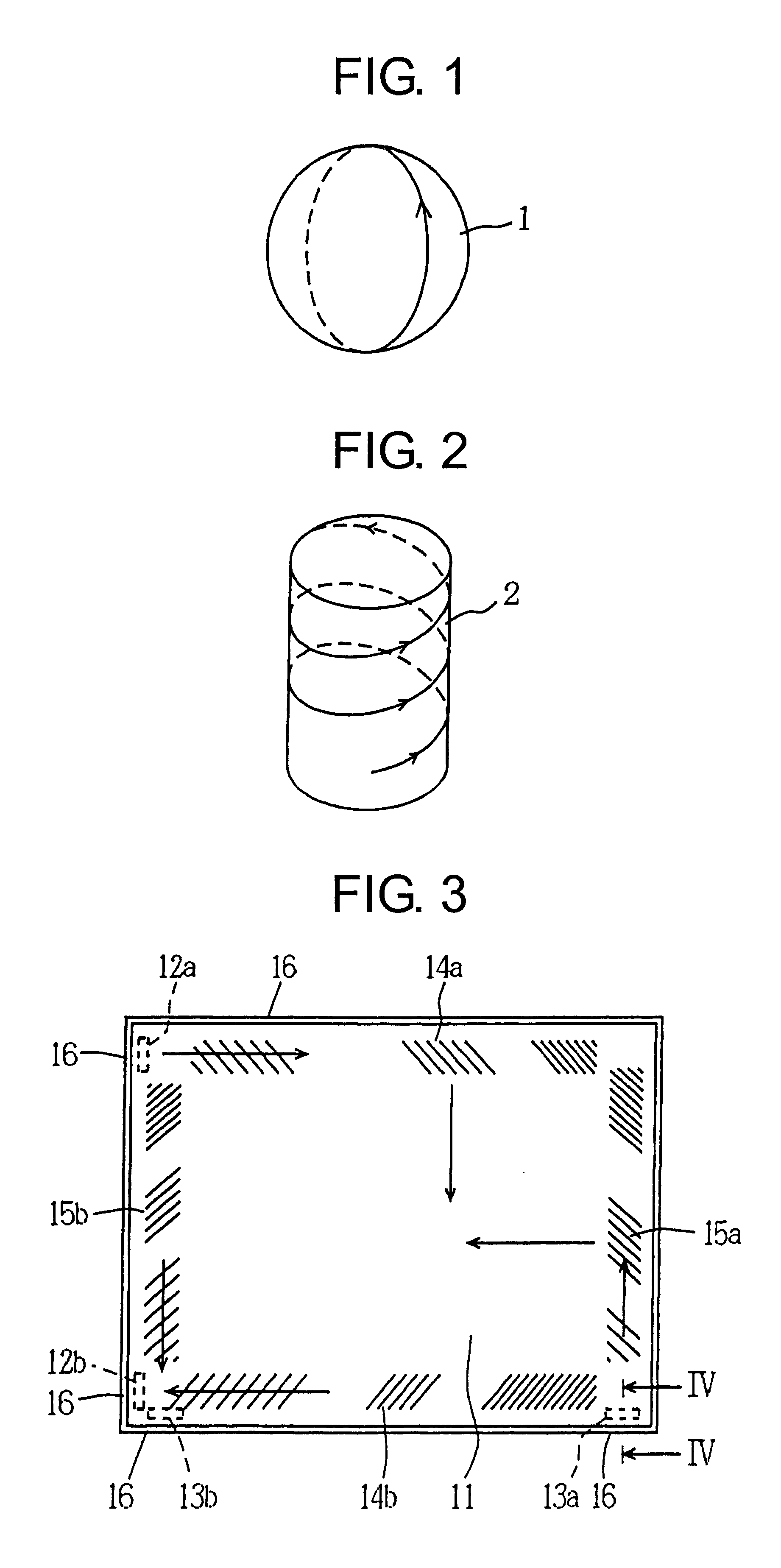
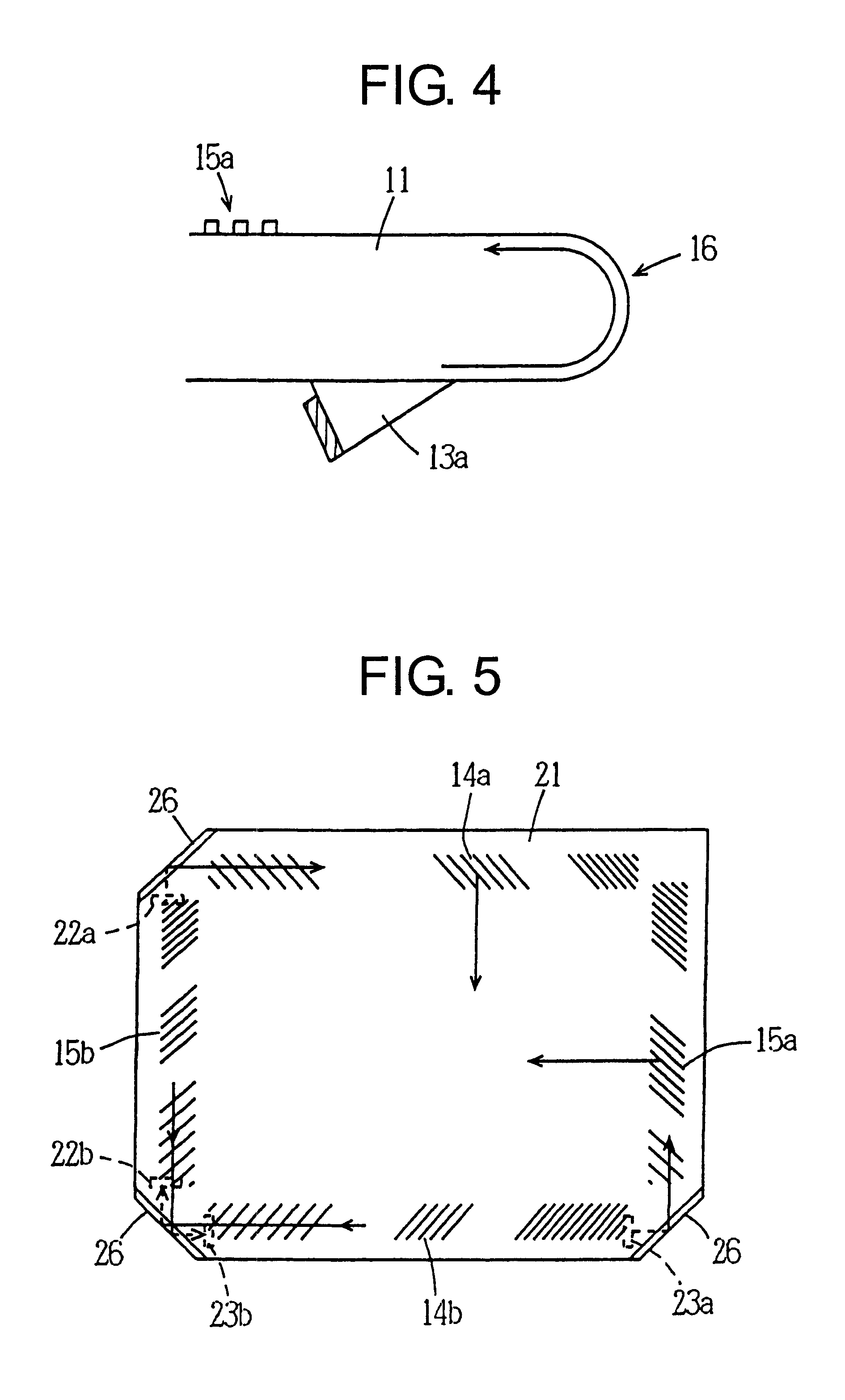
A touch panel for 10.4-inch LCD monitor having the structure shown in FIG. 3 was fabricated using 2.8 mm thickness of soda glass substrate. As a transducer, a plastic wedge-shaped transducer (of about 3 mm height), to which a piezoelectric resonator (of 5.5 MHz resonance frequency) is mounted by an ultraviolet-ray setting adhesive, was applied. A reflecting array was formed by providing a pair of the reflecting array for oscillating side and the reflecting array for receiving side on the peripheral portion of the surface of the glass substrate respectively in the X-axis and Y-axis directions using glass paste by the screen-printing process and firing at 450.degree. C., based upon the Japanese Patent Laid-Open Publication No. 61-239322.

Electric wire cables were connected with the electrode of each piezoelectric resonator by soldering, and these electric wire cables were then connected to a controller through a connector. As a controller, a commercially available ultrasonic system con...

example 2

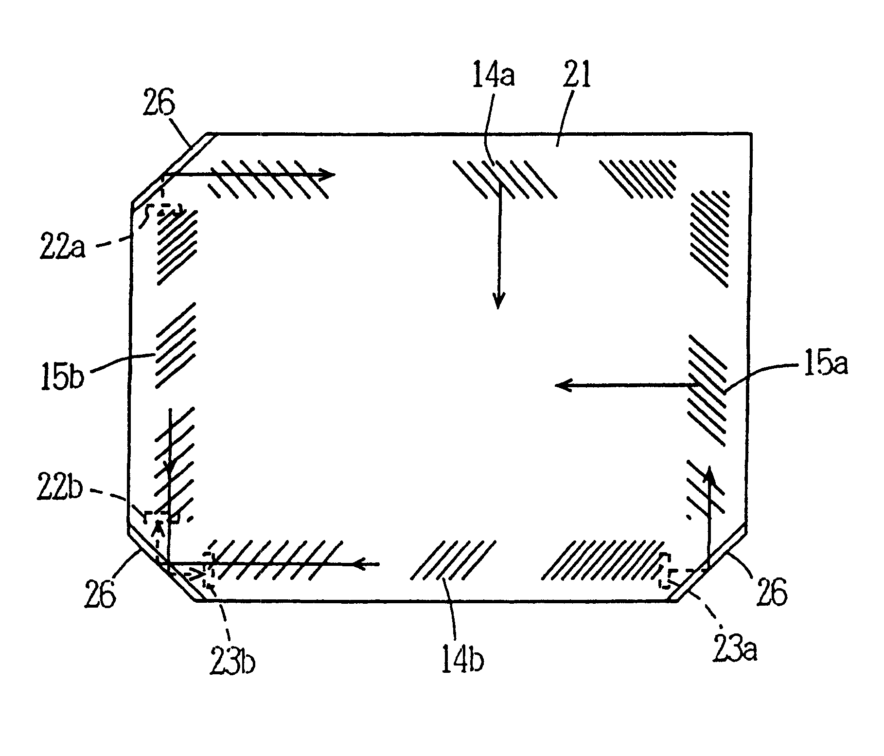
A touch panel for 15-inch dome-shaped CRT monitor having the structure shown in FIG. 5 was fabricated using 2.8 mm thickness of soda glass substrate. A transducer and reflecting array were formed in the same manner as described above. Electric wire cables were connected to electrodes of each piezoelectric resonator by soldering, and these electric wire cables were connected to a controller through a connector. As a controller, a commercially available ultrasonic system controller (1055E101, made by Touch Panel Systems Co.) was applied. A personal computer was connected to the controller to analyze received signals and detect input position.

A CRT of the CRT monitor has a rectangular shape including four chamfered corner portions. In the touch panel corresponding to this CRT, transducers are generally placed in the three corner portions. However, in the chamfered rectangular substrate, since the corner portions for mounting the transducers are formed with the radius (R), the slope pro...


PUM


Abstract

A touch panel comprises a substrate 11 allowing acoustic wave to be propagated and a transducer 13a, mounted to this substrate, for transmitting or receiving the acoustic wave. A chamfered portion 16 is formed in the end face or the corner portion of the substrate 11 to make the acoustic wave turn around and be propagated from the front surface to the rear surface through the end face of the substrate 11. The acoustic wave propagated through the chamfered portion is received by the transducer 13a placed on the rear surface of the substrate 11. The radius (R) of the chamfered portion 16 of the substrate is 0.5 mm or more. This touch panel may prevent from forming raised portions on the front surface of the propagation medium, so that the touch panel may be enhanced in applicability to thin LCD monitors, and simplified in structure.

Description

The present invention relates to a touch panel (or a touch sensor or touch screen) to input / output coordinate information on touch-positions touched with fingers or the like, and more particularly to a touch panel (or a touch-position detecting device) having transmitting and receiving elements to utilize acoustic wave (e.g. surface ultrasonic wave).As primary type of the touch panels, there have been known the surface ultrasonic wave type, the resistance film type, the electrostatic capacity type, the electromagnetic induction type and others. Among these types, the surface ultrasonic wave type includes one known method in which transmitting and receiving transducers are placed opposite each other in both directions of X and Y axes of the surface of a propagation medium, such as a glass substrate, to detect the touch-positions.On the other hand, as a widely popularized method in recent years, there has been known a method in which respective pairs of transmitting and receiving tran...

Claims


Application Information

Patent Timeline
Patent Type & Authority Patents(United States)
IPC IPC(8): G06F3/033G06F3/043G06F3/041G06K11/06
CPCG06F3/0436G06F3/043G06K11/06
Inventor INOUE, SATOSHITANAKA, YOSHIKAZU
Owner TOUCH PANEL SYST
Why Eureka
Try Eureka