Method for manufacture of a directionally solidified columnar grained article

a columnar grained article and directionally solidified technology, applied in the direction of crystal growth process, polycrystalline material growth, chemistry apparatus and processes, etc., can solve the problems of increasing the furnace time required to cast the part, increasing the cost, and difficult to reuse, so as to reduce the secondary misorientation of the columnar grained article, reduce the cost of incremental production, and strong transverse properties

Inactive Publication Date: 2003-05-27
ANSALDO ENERGIA IP UK LTD
View PDF22 Cites 11 Cited by
  • Summary
  • Abstract
  • Description
  • Claims
  • Application Information

AI Technical Summary

Benefits of technology

The multiple grain selector consists of a portion of constrained growth in the main direction of heat flow during solidification (that is, the main direction of solidification) which acts to select grains with a desired primary orientation, and a portion which constrains the grains to grow at least partially in the horizontal (secondary) direction so that it is not possible for any grain or dendrite to grow from cooling plate to the article-defining cavity along a continuous path of purely vertical growth. The advantage of the novel structure is that it shows surprisingly stronger transverse properties (low cycle fatigue life, creep rupture life) than those in prior art columnar grained articles due to the reduced secondary misorientation of the columnar grained article.
This will be achieved for a relatively low incremental cost over the normal process and much lower costs in comparison to using multiple seeds or multiple single crystal selectors known from the state of the art.
Another advantage comes from the possibility of choosing a desired secondary orientation relative to the article or some feature of the article (not just the relative misorientation between adjacent grains or dendrites). For example, it may be preferred to center the distribution of secondary orientations around the main direction of transverse loading in the columnar grained article, so as to further maximise transverse lifetime.
A further advantage of this invention over the prior art of single crystal selectors is that the selectors disclosed herein are much larger and more robust than the smaller selector sections known in the state of the art, and will not suffer from the fragility of the prior art selectors often leading to mold cracking during handling or casting.
A further advantage of the present invention over prior art selectors is that, due to the relatively large cross section of the multi-grain selector, there will still be a substantial amount of heat flow through the metal in the selector to the cooling plate. In some possible embodiments of the invention, with small selector chambers, there will not be a large difference in heat flow to the cooling plate compared to the prior art columnar grained casting processes. This will maintain rapid solidification at the start of casting and help to keep furnace-usage time costs to a minimum.
It will be understood that although the following drawings show relatively large sections for the sake of clarity, the practical use of this invention will minimize the entire selector section size as much as possible to minimize heat flow impacts.

Problems solved by technology

In this sense, starter zones are grain selectors in that they impede the growth of grains of undesirable crystallographic orientations into the article to be manufactured.
These seed crystals are not without problems, being costly to produce and requiring special conditions during casting to produce the desired single grain in the article.
To reduce the cost they are made small, but this also makes them difficult to handle and difficult to reuse.
This increases the furnace time required to cast the part, and hence increases its cost.
The same problems of seeds for single crystal articles would exist for seeds to be used for columnar grained castings--and would be much greater.
The seeds, being composed of several individual single crystals and generally being much larger in surface area than seeds for single crystal articles would be very expensive.
Fitting into the shell mold would be even more problematic.

Method used


Image

  • Method for manufacture of a directionally solidified columnar grained article
  • Method for manufacture of a directionally solidified columnar grained article
  • Method for manufacture of a directionally solidified columnar grained article

Examples


first embodiment

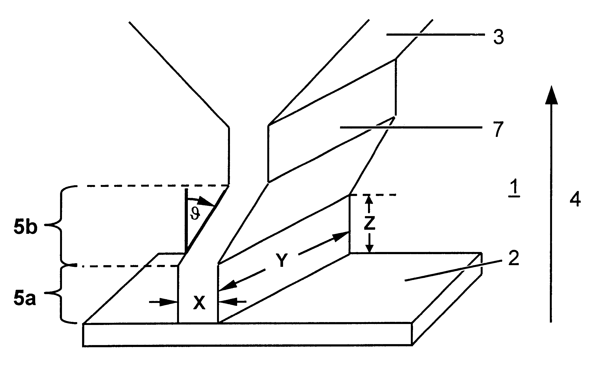
FIG. 1 shows a first embodiment according the invention. A selector section 1 on a cooling plate 2 is shown. The selector section 1 is divided into two stages, the primary selector section 5a and the secondary selector section 5b. The primary selector section 5a of the selector section 1, which is rectangular in cross section in this embodiment and has the dimensions thickness X, length Y and height Z, selects out during solidification those dendrites most favorably oriented with respect to the growth direction 4 but still having random secondary orientations. This is followed by the secondary selector section 5b of imposed growth at an angle to vertical theta (.differential.) which may vary from 1.degree. to 135.degree.. In a preferred embodiment .theta. has a range from 50.degree. to 90.degree. for net horizontal growth component equal at least to the average thickness of the selector passage in this region so that it is not possible for any dendrite to grow from the primary selec...

second embodiment

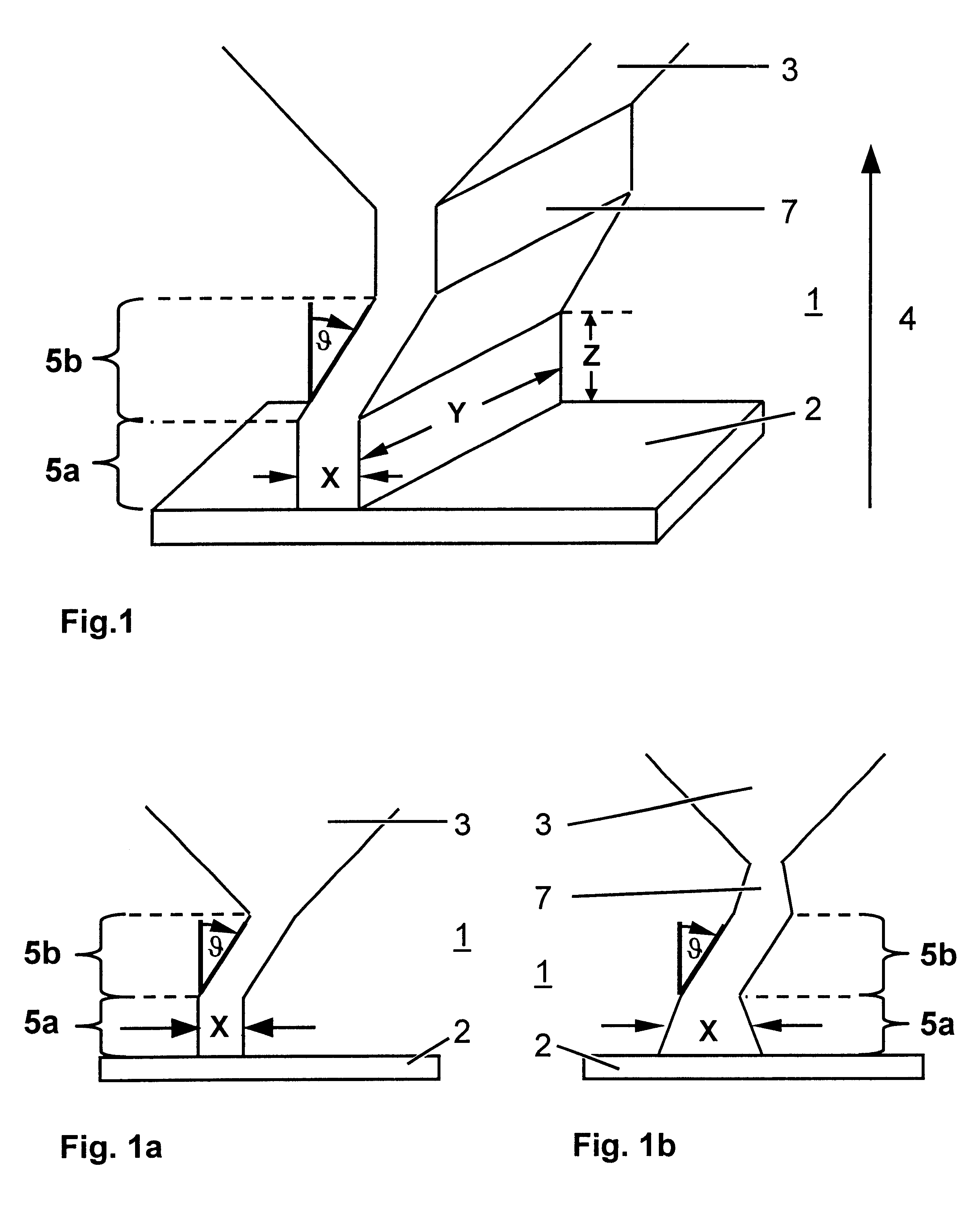
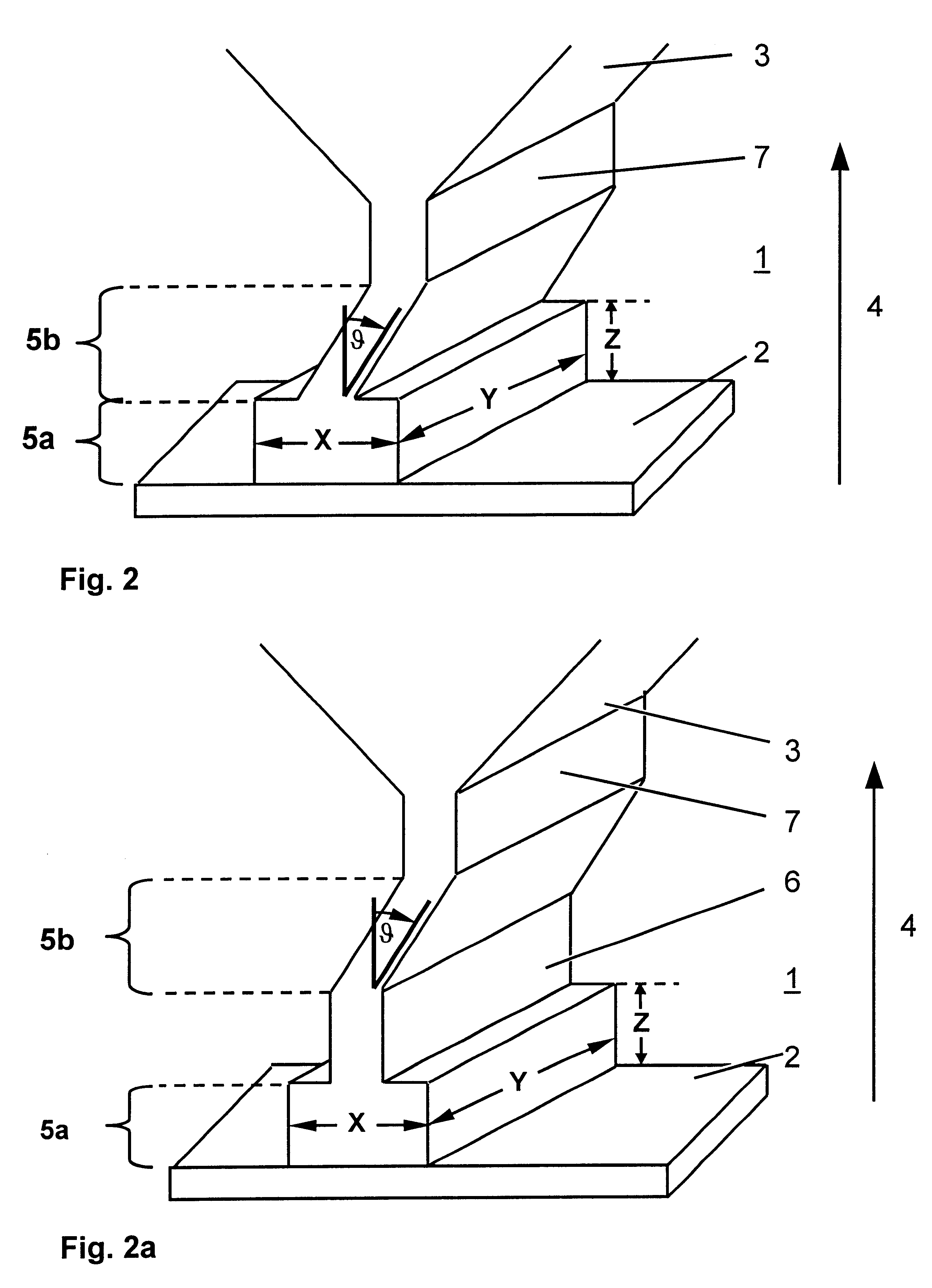
the invention is shown in FIG. 2. The primary selector section 5a is enlarged compared to the thickness of the secondary selector section 5b. The primary selector section 5a may also be tapered into the secondary selector section 5b and may be of any shape so long as solidification is constrained to take place in the vertical direction. This variation is shown in FIG. 2b. The leading passage 7 is omitted in the embodiment of FIG. 2b.

As shown in FIG. 2a the primary selector section 5a may also have a constricted intermediate passage 6 of any length connecting it to the secondary selector section 5b which is more effective for vertical selection. The constricted passage 6 must be smaller in thickness than the base primary selector section 5a but may be the same thickness of the secondary selector section 5b.

third embodiment

FIG. 3 shows the invention in which the primary selector section 5a is removed and the secondary selector section 5b directly contacts the cooling plate 2 and is left with the task of both primary and secondary selection. This arrangement may be possible under certain conditions of casting and would be advantageous to decrease the total height of the selector section 1. Alternatively, the primary selection may be carried out after the secondary as indicated in FIG. 3, with the aforementioned possible design variations on the primary selector section 5a still applicable (e.g. special shape). In this embodiment the leading passage 7 is equal to the primary selector section 5a. As also shown in FIG. 3, the liquid metal maybe fed into the shell mold from an opening in the top of the casting furnace to descend into the selector section 1 cavities from above. The feeding direction 9 is indicated in FIG. 3 with an arrow.


PUM

PropertyMeasurementUnit
angleaaaaaaaaaa
temperatureaaaaaaaaaa
grain structureaaaaaaaaaa

Abstract

A method and an apparatus for manufacturing a directionally solidified columnar grained article with a reduced amount of secondary misorientation of the columnar grains. The method employs a casting assembly comprising a mold with a cavity, a selector section at a lower end of the mold, a heating chamber and a cooling chamber. The mold is fed with a liquid metal and then removed from the heating chamber to the cooling chamber where the columnar grained article is solidified. The article is solidified with at least two dendrites or grains emerging from the selector section and entering the main cavity of the shell mold. Further, the selector section is configured so that no dendrite or grain grows from the bottom of the selector section into the shell mold cavity along a continuous path of purely vertical growth.

Description

The invention relates to an apparatus and a method for manufacturing a directionally solidified columnar grained article.The directional solidification process is a version of investment casting in which a cavity resembling the desired finished piece is defined by a ceramic shell mold. The mold is placed on a cooling surface, preheated to a desired temperature in a high temperature environment, filled with a liquid alloy, and withdrawn from the high temperature environment into a lower temperature environment (defined by a vacuum or liquid coolant or cooling by other means) at a specific rate so as to induce solidification of the liquid alloy in a directional fashion, starting at the cooling plate. A casting furnace is known for example from U.S. Pat. No. 3,532,155, furnaces working with gas cooling are known from the U.S. Pat. No. 3,690,367 or the European patent application EP-A1-749,790, and a LMC furnace is described in U.S. Pat. No. 3,763,926.Directionally solidified articles w...

Claims


Application Information

Patent Timeline
Patent Type & Authority Patents(United States)
IPC IPC(8): C30B11/00
CPCC30B11/00C30B29/52
Inventor FERNIHOUGH, JOHN
Owner ANSALDO ENERGIA IP UK LTD
Why Eureka
Try Eureka