
Method of thermally perforating a heat sensitive stencil

a heat-sensitive stencil and perforation technology, which is applied in the direction of foil printing, transportation and packaging, synthetic resin layered products, etc., can solve the problems of incompatibility of heat shrinkage factor or heat shrinkage stress with actual perforation, difficult to read from tma data, and general incompatibility with sensitivity

Inactive Publication Date: 2003-06-03
RISO KAGAKU CORP
View PDF13 Cites 1 Cited by
  • Summary
  • Abstract
  • Description
  • Claims
  • Application Information

AI Technical Summary

Benefits of technology

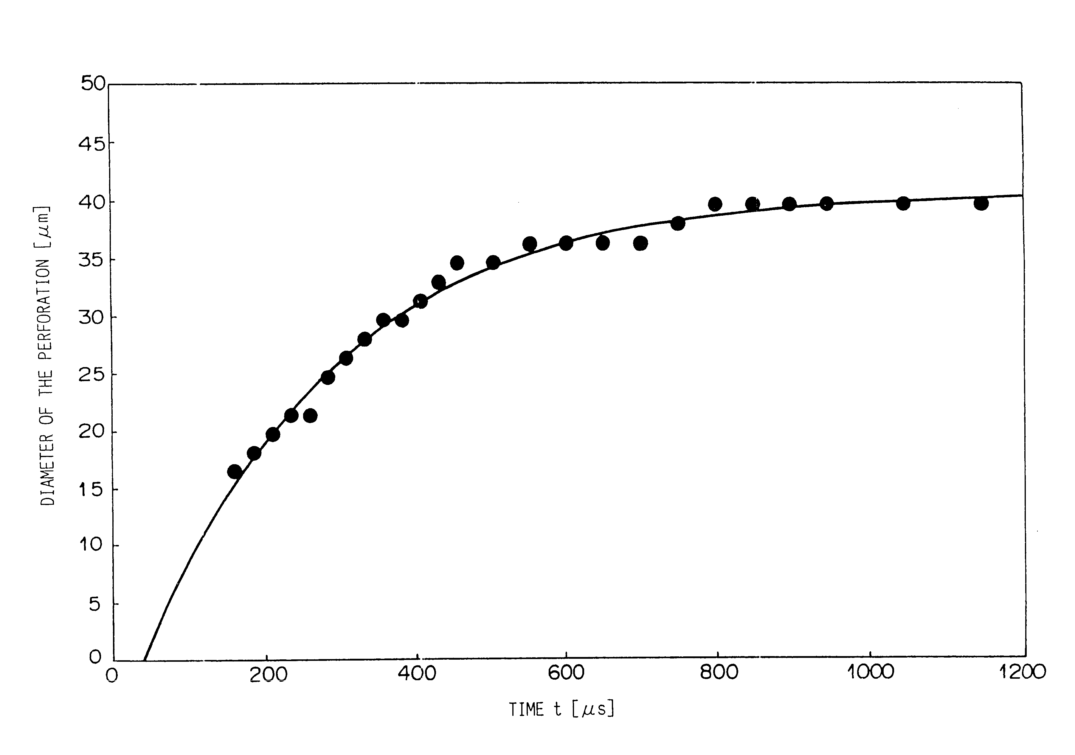
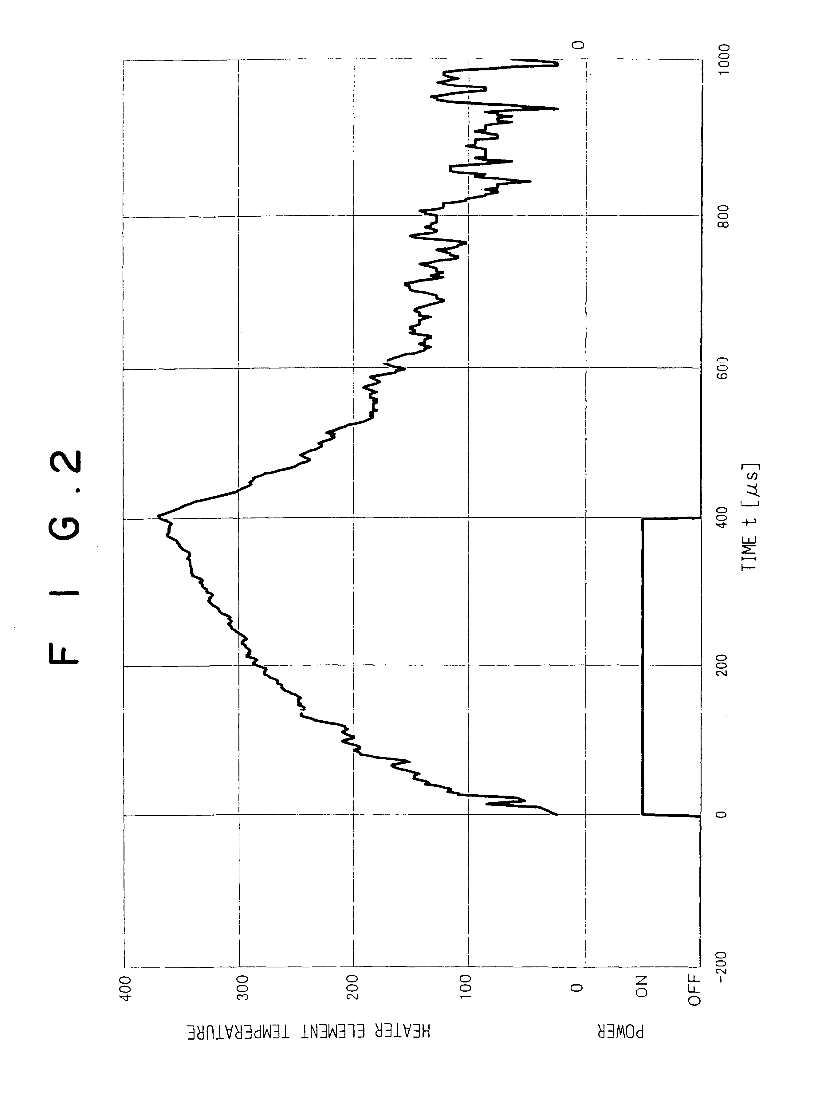
When supply of energy to the heat source is cut when the quotient obtained by dividing by the energizing time a maximum diameter of the perforation at the time at which supply of energy to the heat source is cut is in the range of 0.015 m / s to 0.055 m / s, the image can be high in reproducibility and high in quality. More specifically when the quotient is in the range, the perforating speed is low, and accordingly, the thermoplastic resin film can well follow change in temperature of the heat source. That is, the shape of the perforation in the film faithfully reflects the temperature contrast on the heat source, whereby the perforations can be uniform in shape and size and the amount of ink to be transferred through the stencil can be constant, which results in a high quality image. Thus the method and the apparatus are very useful when an especially high image is required.
When supply of energy to the heat source is cut when the quotient obtained by dividing by the energizing time a maximum diameter of the perforation at the time at which supply of energy to the heat source is cut is in the range of 0.08 m / s to 0.23 m / s, sensitivity to perforation and perforating speed can be high. More specifically when the quotient is in the range, the perforating speed is high, and accordingly, the total energy supplied to the heat source to obtain a perforation of a given size can be reduced by shortening the energizing time and / or reducing energy supplied to the heat source per unit time. When the total energy supplied to the heat source is reduced, heat accumulated in the heat source and / or heat transfer parts can be reduced, whereby the number of printings obtained per unit time can be enlarged.
The values of the diameter and the area of the perforations are not as measured in the thermoplastic film laminated on the porous support sheet (to form a heat-sensitive stencil) but as measured in the thermoplastic film by itself. This is because it is very difficult to observe the state of perforation and to measure the diameter and / or the area of the perforation in a state where the thermoplastic film is laminated on the porous support sheet. However, the state of perforation (the diameter and / or the area of the perforation) as measured in the thermoplastic film by itself has a high correlation with that as measured in the thermoplastic film laminated on the porous support sheet. FIGS. 7 and 8 show the correlation. In FIG. 7, the ordinate represents the diameters of the perforations in the final state when a heat-sensitive stencil material (a thermoplastic film and a porous support sheet laminated together) is perforated under various conditions and the abscissa represents the diameters of the perforations in the final state when the same thermoplastic film as that employed in the heat-sensitive stencil material is perforated by itself under the same conditions. The correlation coefficient of the graph shown in FIG. 7 is 0.913. In FIG. 8, the ordinate represents the areas of the perforations in the final state when a heat-sensitive stencil material (a thermoplastic film and a porous support sheet laminated together) is perforated under various conditions and the abscissa represents the areas of the perforations in the final state when the same thermoplastic film as that employed in the heat-sensitive stencil material is perforated by itself under the same conditions. The correlation coefficient of the graph shown in FIG. 8 is 0.9319. Thus it will be understood that the state of perforation in the thermoplastic film by itself can represent the state of perforation in the heat-sensitive stencil material comprising the thermoplastic film laminated with a porous support sheet.

Problems solved by technology

Further, the measurement is static and does not reflect the actual perforation.
Thus the reported heat shrinkage factor or heat shrinkage stress does not conform to the actual perforation.
Accordingly, the properties of the film concerning to the degree to which the perforations are discrete by pixel and the shape of the perforations is stabilized are generally incompatible with the sensitivity to perforation of film and the speed at which the film is perforated.
Further, it is difficult to read from the TMA data the performance of the film representing the perforating speed, the stability of the shape of perforations and the like except the sensitivity to perforation.
Even about the sensitivity to perforation, it is difficult to estimate the difference in the sensitivity to perforation between film samples which are slightly different from each other, for instance, in TMA curve since it is actually impossible to prepare a variety of film samples which are different from each other in one or more particular factor such as the TMA curve with the other factors held to be the same.
Accordingly, when a suitable kind of resin film is to be selected, stencils must be actually made using a variety of resin film samples, which adds to the development cost.
Accordingly, it has been very difficult to know, without experience and sense, how the physical properties of the resin film should be changed on the basis of the result of experiment in order to obtain a desirable form of perforation, which has been made difficult development of new products and improvement of the performance of the products.
Unsatisfactory design of the performance of the resin film can result in the case where the sensitivity to perforation and perforating speed are too poor to obtain a high-resolution stencil under a practical condition though the perforations are discrete and substantially uniform in shape or in the case where the perforations are not discrete and not uniform in shape though the sensitivity to perforation and perforating speed are satisfactory.
Thus, it has been impossible to develop, on the basis of conventional data experimentally obtained, a method of and an apparatus for making a stencil by thermally perforating a thermoplastic resin film of heat-sensitive stencil material, and a thermoplastic resin film for heat-sensitive stencil material in which demands for uniformity in shape of perforations, sensitivity to perforation and perforating speed are all satisfied.
When supply of energy to the heat source is cut before the quotient obtained by dividing by the energizing time a maximum diameter of the perforation at the time at which supply of energy to the heat source is cut reaches 0.015 m / s, sensitivity to perforation deteriorates and the perforations cannot be formed at a satisfactory speed.
Whereas, when supply of energy to the heat source is cut after the quotient obtained by dividing by the energizing time a maximum diameter of the perforation at the time at which supply of energy to the heat source is cut exceeds 0.23 m / s, the perforations cannot be discrete and at the same time the shape of the perforations becomes unstable.
Further, in this case, since the heat source is heated to a high temperature, the heat source is apt to be damaged.
When supply of energy to the heat source is cut before the quotient reaches 0.06 m / s, sensitivity to perforation and perforating speed are unsatisfactory, whereas when supply of energy to the heat source is cut after the quotient exceeds 0.075 m / s, high performance cannot be realized in discreteness of the perforations and stability in shape of the perforations.
When the mean enlarging speed is smaller than 0.015 m / s, sensitivity to perforation deteriorates and the perforations can not be formed at a satisfactory speed.
Whereas, when the mean enlarging speed is larger than 0.23 m / s, the perforations cannot be discrete and at the same time the shape of the perforations becomes unstable.
Further, in this case, since the heat source is heated to a high temperature, the heat source is apt to be damaged.
When the mean enlarging speed is smaller than 0.06 m / s, sensitivity to perforation and perforating speed are unsatisfactory, whereas when the mean enlarging speed is larger than 0.075 m / s, high performance cannot be realized in discreteness of perforations and stability in shape of the perforations.
This is because it is very difficult to observe the state of perforation and to measure the diameter and / or the area of the perforation in a state where the thermoplastic film is laminated on the porous support sheet.
When the melting point is higher than 240.degree. C., high sensitivity to perforation cannot be obtained, whereas when the melting point is lower than 150.degree. C., the thermal dimensional stability of the film deteriorates and the film curls during manufacture of the stencil or during storage of the stencil, whereby printing image quality becomes unsatisfactory.

Method used


Image

  • Method of thermally perforating a heat sensitive stencil
  • Method of thermally perforating a heat sensitive stencil
  • Method of thermally perforating a heat sensitive stencil

Examples


embodiment 1

The same polyester resin as in the embodiment 1 was cast on a cooling drum and un-oriented sheet 21 .mu.m thick was obtained. Then the un-oriented sheet was oriented to 3.2 times in the longitudinal direction by a series of heated rolls at 90.degree. C., and the longitudinally oriented sheet was further oriented to 3.2 times in the transverse direction by a tenter transverse stretching machine at 95.degree. C. Further, the sheet was subjected to heat treatment at 140.degree. C. f or 10 seconds in the tenter, whereby biaxially oriented film 2.0 .mu.m thick was prepared. Further a heat--sensitive stencil material was obtained in the same manner as in the

The film by itself was perforated under the conditions shown in the following table 1 and by the use of the stencil material thus obtained, a stencil was made under the conditions shown in the following table 1 and printing was done by the use of the stencil.


PUM

PropertyMeasurementUnit
thicknessaaaaaaaaaa
thicknessaaaaaaaaaa
thicknessaaaaaaaaaa

Abstract

A stencil is made by thermally forming perforations arranged in both a main scanning direction and a sub-scanning direction in a thermoplastic resin film of heat-sensitive stencil material by the use of a heat source which is heated through supply of energy. Supply of energy to the heat source is cut so that the quotient obtained by dividing a maximum diameter of a perforation at the time at which supply of energy to the heat source is cut by the energizing time is not smaller than 0.015 m / s and not larger than 0.23 m / s.

Description

1. Field of the InventionThis invention relates to a method of and an apparatus for making a stencil by thermally perforating a thermoplastic resin film of heat-sensitive stencil material by a thermal head or the like, and to a heat-sensitive stencil material. More particularly, this invention relates to improvement in shape of perforations, printing quality and stencil making speed.2. Description of the Related ArtMethods of making a heat-sensitive stencil are broadly divided into a method in which the resin film side of the heat-sensitive stencil material is brought into close contact with an original bearing thereon an image depicted in a carbon-containing material and the resin film is perforated by heat generated by the image upon exposure to infra-red rays and a method in which the resin film of the heat-sensitive stencil material is imagewise perforated by two-dimensionally scanning the resin film side of the heat-sensitive stencil material with a device such as a thermal hea...

Claims


Application Information

Patent Timeline
Patent Type & Authority Patents(United States)
IPC IPC(8): B32B3/24B32B27/00B41C1/14B41C1/055B41N1/24
CPCB32B3/266B41C1/144B32B27/00Y10T428/24331B32B2305/026B32B27/12B32B27/10B32B2329/04B32B2323/10B32B2323/04B32B27/08B32B2262/023B32B27/32B32B2398/10B32B5/022B32B2367/00B32B2305/18
Inventor OHSHIMA, KENJINAKAMURA, JUN
Owner RISO KAGAKU CORP
Learn More