Fluid flow control for cool, efficient fuel cell operation

a technology of efficient fuel cell and flow control, which is applied in the direction of fuel cell details, fuel cells, electrochemical generators, etc., can solve the problems of loss of efficiency in random areas of the fuel cell stack, and achieve the effects of reducing the maximum temperature in each cell, increasing air utilization, and high performan

Inactive Publication Date: 2003-06-03
AUDI AG
View PDF4 Cites 23 Cited by
  • Summary
  • Abstract
  • Description
  • Claims
  • Application Information

AI Technical Summary

Benefits of technology

Objects of the invention, in a PEM fuel cell, include: assuring maximum recovery of product water within the fuel cell stack; achieving high performance with increased air utilization; reducing the maximum temperature in each cell of the stack; providing a more uniform temperature profile across each cell of the stack; achieving a higher coolant exit temperature in order to enhance waste heat rejection while having an adequately low coolant inlet temperature to promote condensation in the exiting oxidant reactant gas flow as well as the exiting fuel reactant gas flow; and reducing the flow of coolant in each cell.
This invention is predicated in part on the recognition that when fuel reactant flow fields are not dead ended, significant water can be carried out of the fuel cell in the fuel reactant gas exhaust, and is predicated in part on the concept that a balance maintained between rich and partially depleted oxidant reactant gas, partially depleted and rich fuel reactant gas, and coolant temperature will significantly reduce the highest temperature in each fuel cell and commensurately provide a more even temperature profile across each fuel cell.
The invention has been shown to reduce the maximum temperature of a fuel cell stack by over 15.degree. F. (about 18.degree. C.), while at the same time reducing the coolant flow by about half and increasing the overall oxidant utilization to near 80%. The invention reduces parasitic power loss by allowing smaller pumps for the oxidant reactant gas and for the coolant. The invention causes substantially the warmest part of the fuel cell to be near the coolant exit, which aids in waste heat rejection by permitting significant reduction in the size of an external heat rejection heat exchanger (such as the conventional radiator of an electric vehicle powered by a fuel cell). The condensation of moisture in the exiting fuel also heats the incoming coolant, raising the temperature of the fuel cell stack in that area somewhat, in turn raising the temperature, and thus the vapor pressure, of the incoming air in an adjacent area of the stack, thereby improving humidification of the incoming air.

Problems solved by technology

However, extremely high overall air utilization results in loss of efficiency in random areas of the fuel cell stack.

Method used


Image

  • Fluid flow control for cool, efficient fuel cell operation
  • Fluid flow control for cool, efficient fuel cell operation
  • Fluid flow control for cool, efficient fuel cell operation

Examples


Embodiment Construction

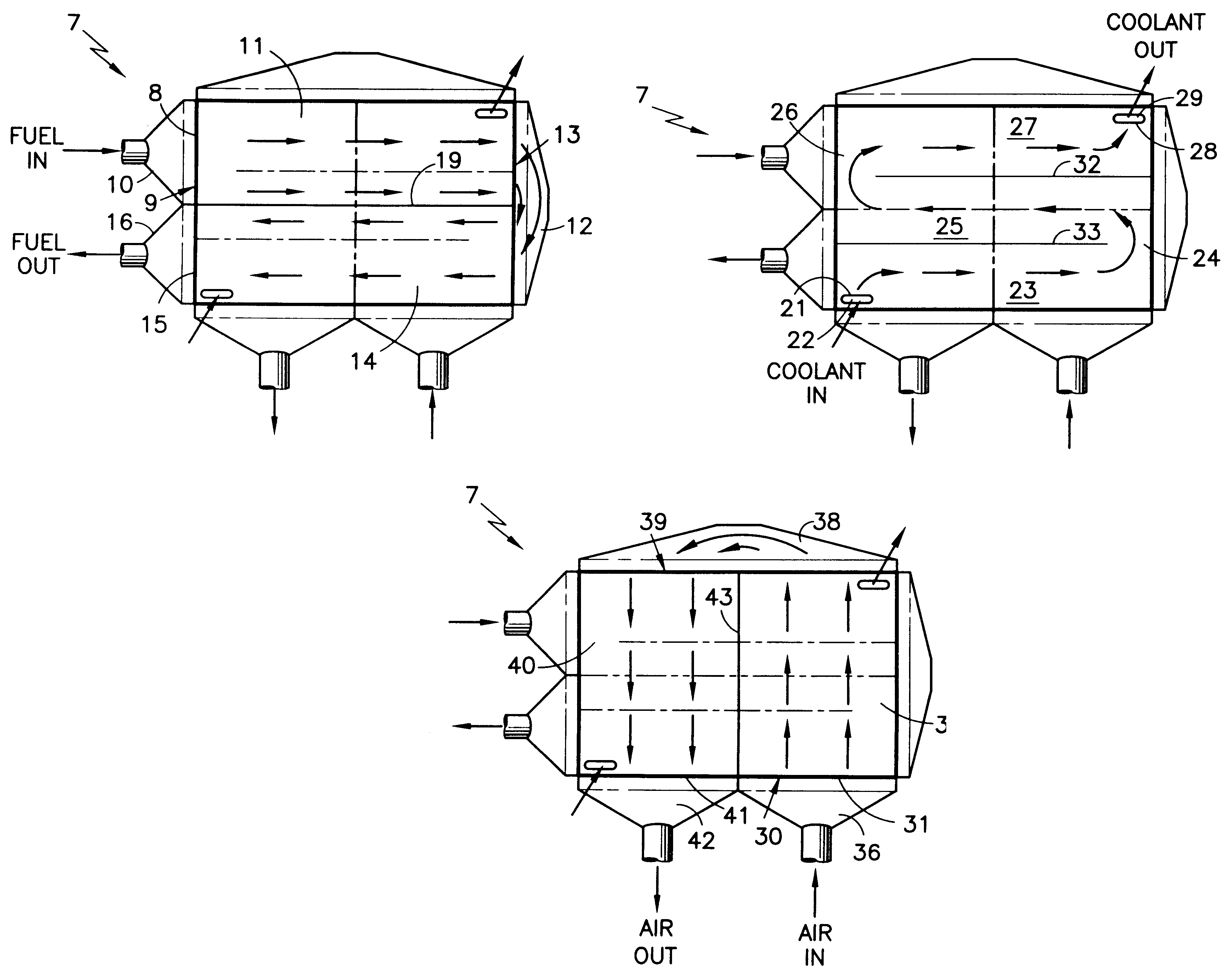
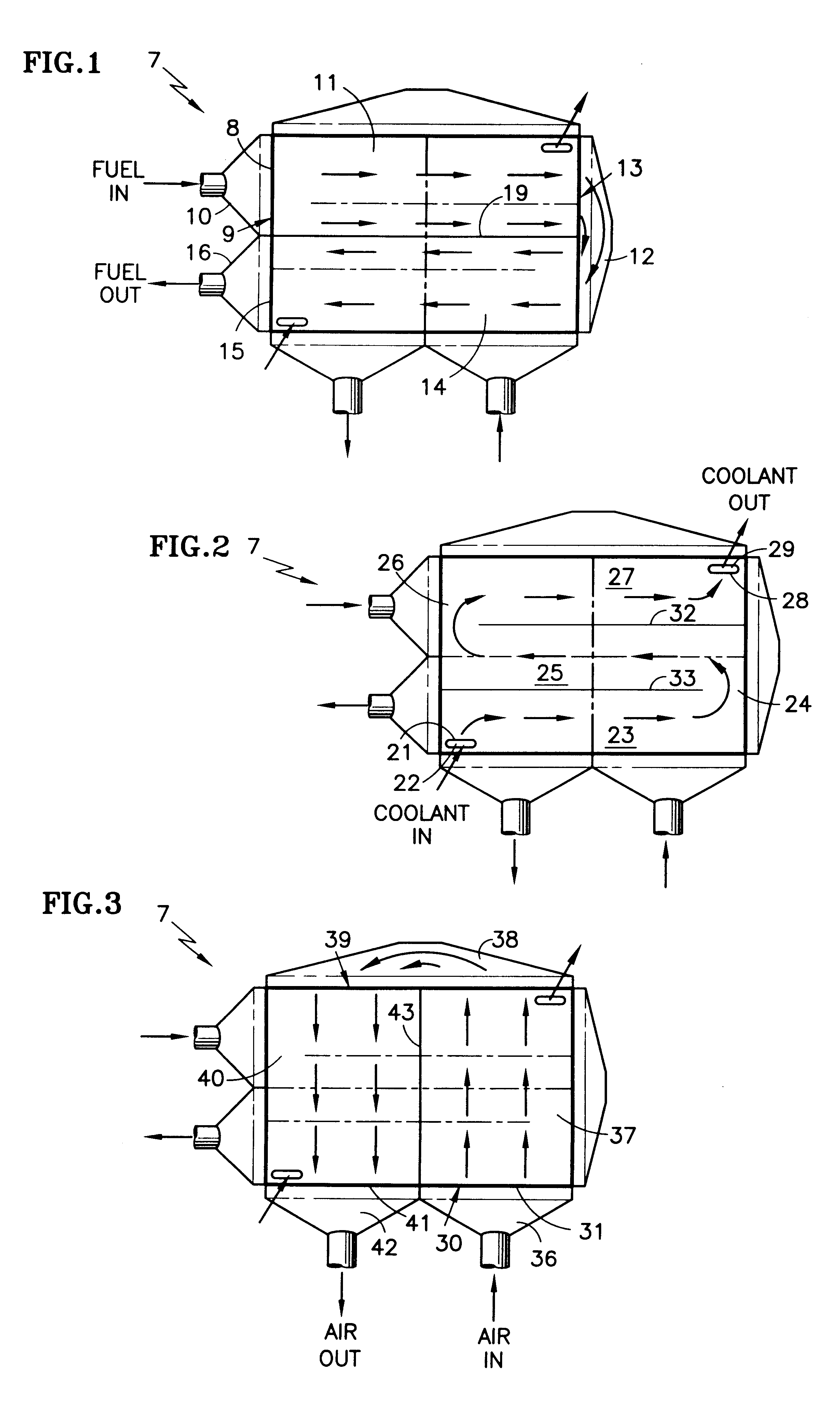
Referring to FIGS. 1-3, each fuel cell of a fuel cell stack 9 includes a fuel inlet 8 at a first end edge 9 of the fuel cell, fed by a fuel inlet manifold 10, a first-pass fuel flow field 11, a fuel turnaround manifold 12 at a second end edge 13, a second-pass fuel flow field 14, and a fuel outlet 15 at the first end edge 9, which feeds a fuel outlet manifold 16. The delineation between first pass 11 and second pass 14 flow fields is illustrated by a line 19 which is shown solid in FIG. 1 and as a double dot dash line in FIGS. 2 and 3. Each fuel cell of the fuel cell stack 9 also includes a coolant inlet 21 fed by an internal coolant inlet manifold 22, a first straight flow field portion 23, a first turnaround flow field portion 24, a second straight flow field portion 25, a second turnaround flow field portion 26, a third straight flow field portion 27, and a coolant outlet 28 which feeds into an internal coolant outlet manifold 29. The demarcation between the direction of coolant ...


PUM

PropertyMeasurementUnit
temperatureaaaaaaaaaa
exit temperatureaaaaaaaaaa
temperatureaaaaaaaaaa

Abstract

A fuel cell stack (7) has a two-pass fuel flow field (11, 14) extending from a fuel inlet (8) around a fuel turnaround manifold (12) to a fuel outlet (15). The stack has two air flow fields (37, 40) extending from an air inlet (32) through an air turnaround manifold (38) to an air outlet (41), the air outlet (41) being adjacent to the fuel outlet (15). The stack includes a coolant flow field (23, 25, 27) which extends from a coolant inlet (21) to a coolant outlet (28), the coolant inlet being adjacent to both the fuel outlet and the air outlet. The fluid flow configuration provides lower temperature, a more even temperature profile, a higher coolant exit temperature, and permits operation with higher air utilization and lower coolant flow.

Description

This invention relates to fuel cells, such as proton exchange membrane (PEM) fuel cells, in which the fuel reactant gas outlet and the oxidant reactant gas outlet are both adjacent to the coolant inlet thereby providing a more uniform temperature profile across each cell of the fuel cell stack, a lower maximum temperature in each cell of the fuel cell stack, a higher coolant exit temperature, higher water recovery, and further permitting operation with higher air utilization and lower coolant flow.It is known that, in PEM fuel cells, the membrane must be wet in order to maintain high process efficiency and to avoid membrane degradation which will result in reactant gas crossover. Each proton formed at the anode will drag molecules of water with it as it passes through the membrane to the cathode side, thereby creating a water-pumping effect commonly known as proton drag. The water thus has to be replenished at the anode side of the membrane, continuously, for efficient operation. On...

Claims


Application Information

Patent Timeline
Patent Type & Authority Patents(United States)
IPC IPC(8): H01M8/02H01M8/04H01M8/24H01M8/10
CPCH01M8/0258H01M8/0267H01M8/2485H01M8/04007Y02E60/50H01M8/04089H01M8/2484H01M8/2483
Inventor YANG, DELIANGKING, CONSTANCE J.
Owner AUDI AG
Why Eureka
Try Eureka