
Valve device

a valve and valve body technology, applied in the direction of valve operating means/releasing devices, machines/engines, mechanical equipment, etc., can solve the problems of spring elements exerting undesirable lateral forces on the magnet armature support and the sealing seat, and cannot be measured or only measured

Inactive Publication Date: 2003-06-17
ROBERT BOSCH GMBH
View PDF8 Cites 23 Cited by
  • Summary
  • Abstract
  • Description
  • Claims
  • Application Information

AI Technical Summary

Benefits of technology

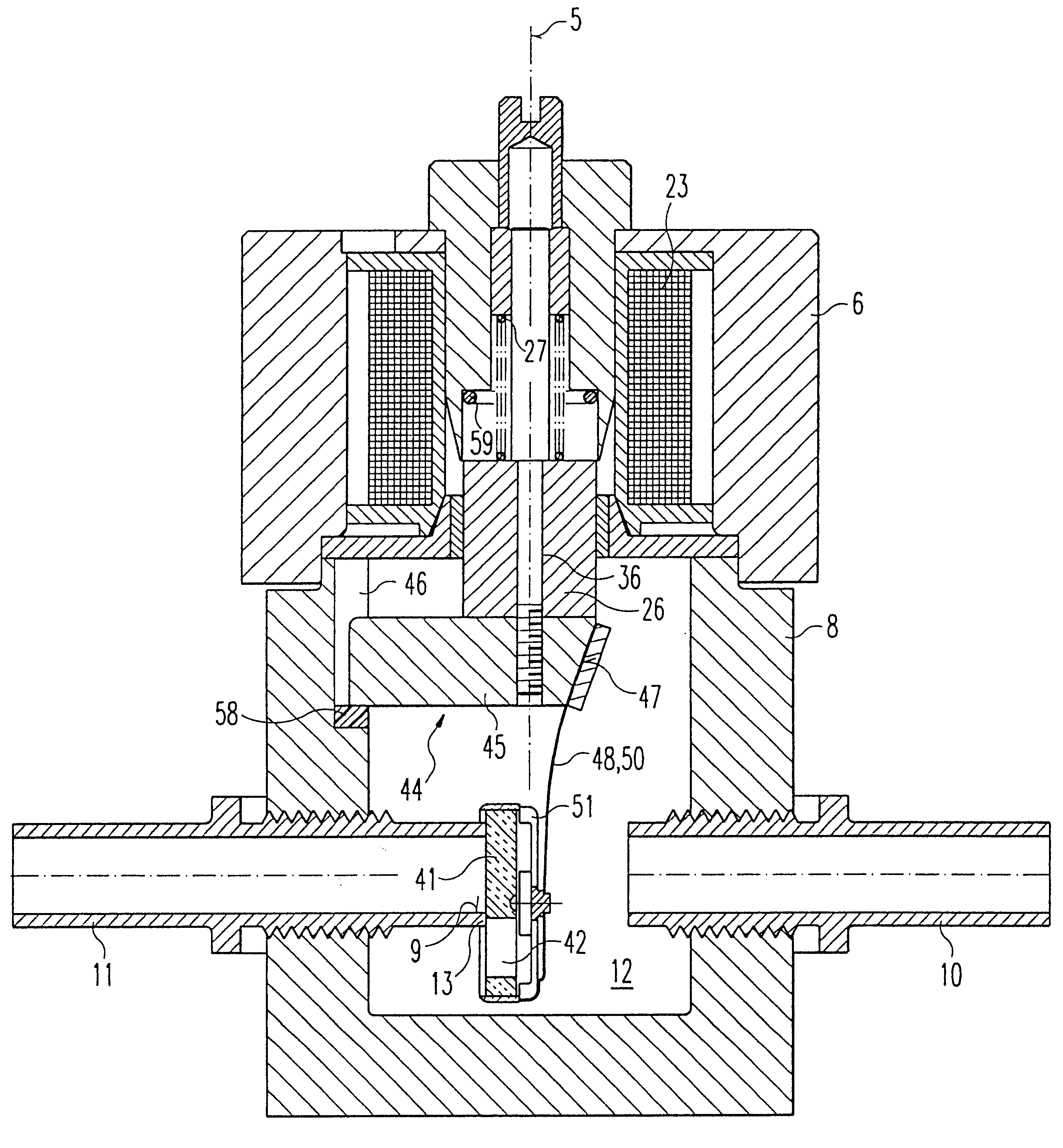
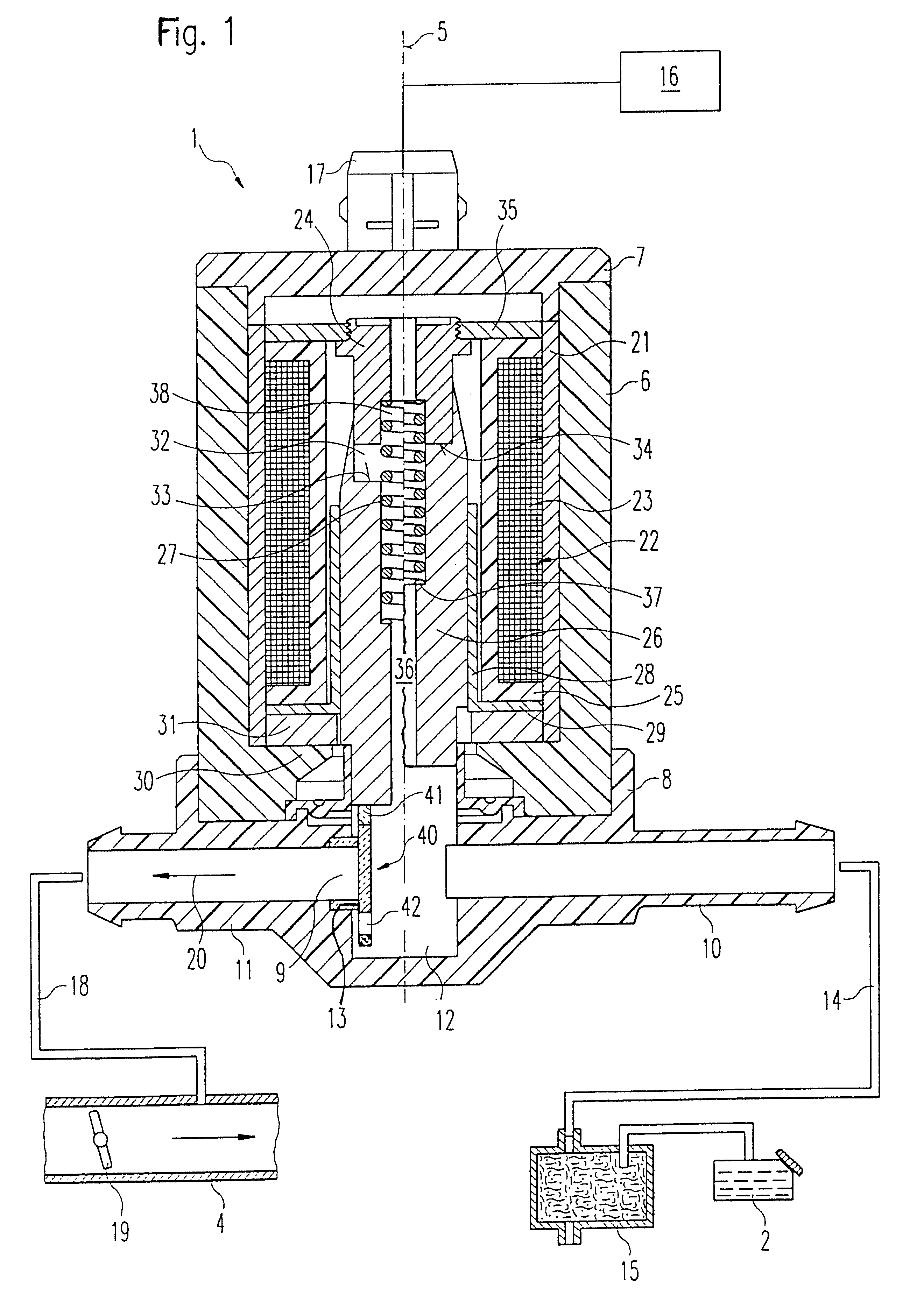
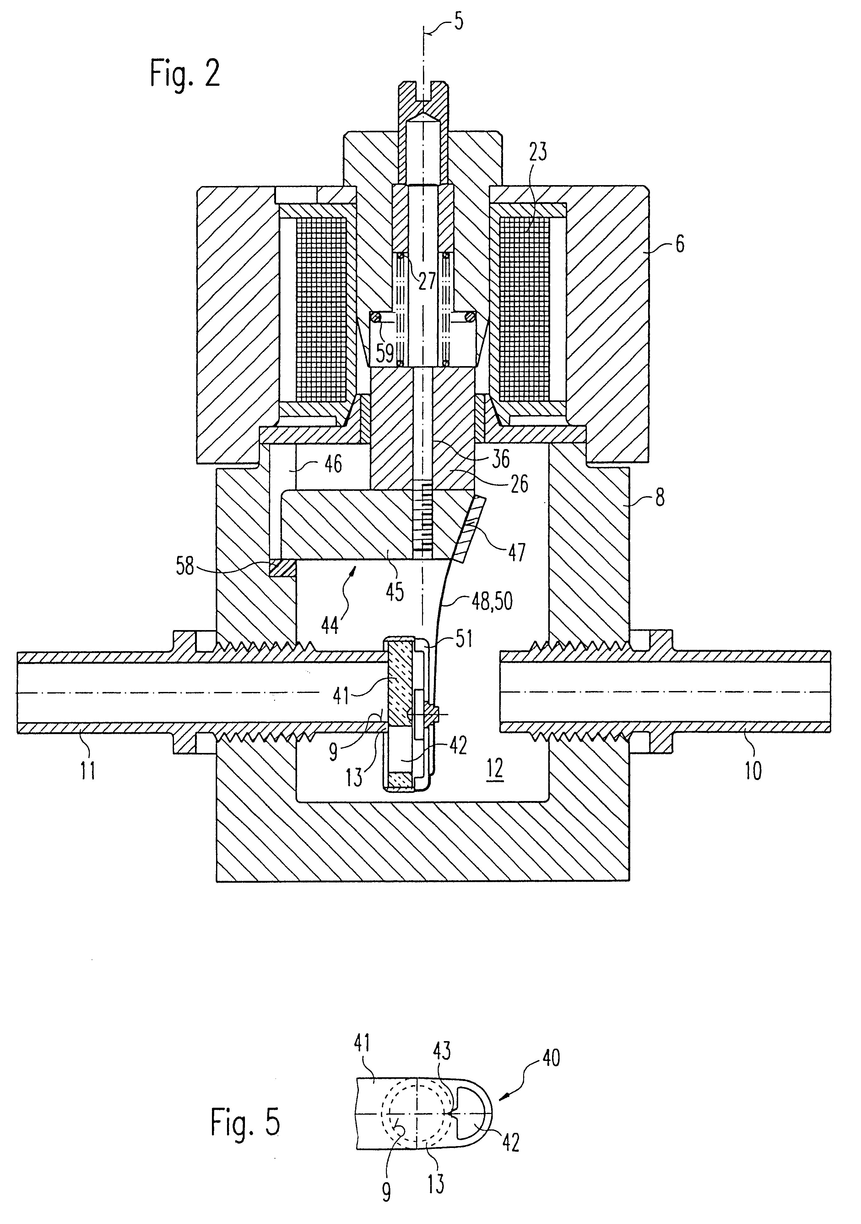
The valve device has the advantage over the prior art that due to the construction of the spring element with a leaf spring, which is connected to both the armature and the closing body, the entire apparatus of the closing body and spring element moves along with the stroke of the armature. As a result of this, no disruptive lateral forces occur at the spring element and at the same time, manufacture tolerances of the sealing seat and closing body can be compensated for so that the sealing seat of the outlet fitting is sealed better and more reliably.The valve device has an advantage that the spiral spring of the spring element deforms exclusively in the direction of its longitudinal axis during the stroke motion of the armature so that here, too, no lateral forces occur at the spring element which could lead to sealing problems. To this end, it is particularly advantageous to rotatably support the spring element in the valve housing so that the stroke motion of the armature produces a rotating motion of the spring element. Likewise, the spring element can be disposed in an advantageously stationary fashion in the valve housing and at the same time, the spring element is not connected to the closing body which means that the closing body can move along with the stroke motion of the armature while the spring element remains unchanged in its position.The valve devices according to the invention are furthermore suitable for engines with gasoline direct injection since large scavenging quantities of fuel vapor can also be conveyed without trouble through the valve devices. Furthermore, the valve devices can be operated in both a continuous and pulsed fashion with high and low frequencies.Other advantageous embodiments and improvements of the valve devices disclosed are possible by means of the measures disclosed herein after.It is particularly advantageous that the fastening device of the closing body on the armature is guided in a housing groove in the valve housing in order to prevent the armature and the components connected to it from rotating or tilting and therefore to prevent a leak at the sealing seat.Exemplary embodiments of the invention are shown in a simplified form in the drawings and will be explained in detail in the subsequent description.FIG. 1 is a longitudinal section through a first exemplary embodiment of a valve device embodied according to the invention,FIG. 2 is an enlarged, slightly modified sectional representation of the apparatus of the closing body according to the first exemplary embodiment from FIG. 1,FIG. 3 is an enlarged sectional representation of a second exemplary embodiment of a valve device embodied according to the invention,FIG. 4 is an enlarged sectional representation of a third exemplary embodiment of a valve device embodied according to the invention,FIG. 5 is a top view of a closing body of the valve device.

Problems solved by technology

Because its composition cannot be measured or can only be measured at a very high-cost, the regenerating flow represents a considerable impedance for the lambda closed-loop control since in addition, the specific density of fuel vapor is approximately twice as high as that of air.
In this embodiment, the spring element must move along with the valve stroke so that as a result of being deformed in a direction radial to its longitudinal axis, the spring element exerts undesirable lateral forces on the magnet armature support and on the sealing seat.
Furthermore, the sealing disk can therefore tilt in its provided mount and sealing problems arise at the sealing seat of this tank ventilation valve.

Method used


Image

  • Valve device
  • Valve device
  • Valve device

Examples


Embodiment Construction

The valve device 1 which is shown in a longitudinal section FIG. 1 is used for the metered introduction of fuel vapor, which has evaporated from a fuel tank 2 of an internal combustion engine, not shown, in particular a mixture-compressing engine with externally supplied ignition, into an intake tube 4 of the engine. The valve device 1 is part of a fuel vapor retention system described at the beginning.

The valve device 1 has a valve housing, which is comprised for example of three parts, including a cylindrical base housing 6, a housing cover 7 that can be placed on the base housing 6, and a bottom housing part 8. The cylindrical base housing 6, the housing cover 7, and the bottom housing part 8 are preferably made of plastic, for example through the use of plastic injection molding technology.

The bottom housing part 8 has an inlet fitting 10 and an outlet fitting 11 which respectively feed into an inner chamber 12 of the valve device 1, which consequently represents a connection be...


PUM


Abstract

The current invention relates to a valve device (1), in particular for tank ventilation in motor vehicles, having a valve housing (6, 7, 8) with an inlet fitting (10) and an outlet fitting (11), having an armature (26) that is provided inside the valve housing (6, 7, 8) and can be moved by means of an electromagnet (22), having a closing body (40) that is connected to the armature (26) and closes a sealing seat (13) of the outlet fitting (11) when the electromagnet (22) is without power and opens it when the electromagnet (22) is supplied with power wherein the free cross sectional area between the inlet fitting (10) and the outlet fitting (11) can be continuously changed, and having a spring element (50) which presses the closing body (40) with a slight pressure against the sealing seat (13). In order to assure a reliable seal of the sealing seat (13) in a simple manner, according to a first embodiment according to the invention, the spring element (50) is comprised of a leaf spring (48) which is connected on the one end to the armature (26) and on the other end to the closing body (40) and furthermore, is pre-stressed against the closing body (40). As an alternative embodiment possibility, a spring element (50) with a spiral spring (49) is proposed, which deforms exclusively in the direction of its longitudinal axis even during the stroke motion of the valve device (1).

Description

PRIOR ARTThe invention is based on a valve device, in particular for tank ventilation in motor vehicles.A valve device of this kind is used to regenerate the activated charcoal in the fuel vapor retention system for fuel circuits in motor vehicles as described for example in the reference Bosch--Technische Unterrichtung, Motormanagement Motronic [Bosch--Technical Instruction, Engine Management Motronics], 2.sup.nd edition, August 1993, pp. 48 and 49. Fuel retention systems limit HC emissions and are equipped with an activated charcoal container to which a ventilation line leads from the fuel tank. The activated charcoal retains the fuel vapor and permits only the air to escape into the atmosphere, which simultaneously provides for a pressure compensation. In order to repeatedly regenerate the activated charcoal, another line leads from the activated charcoal container to an intake tube in which a vacuum is produced when the engine is running, which causes air to flow from the atmosp...

Claims


Application Information

Patent Timeline
IPC IPC(8): F16K3/18F02M25/08F16K3/02F16K31/06
CPCF16K3/18F02M25/0836
Inventor KRIMMER, ERWINSCHULZ, WOLFGANGMIEHLE, TILMAN
Owner ROBERT BOSCH GMBH
Learn More