
Transmission for use in the power trains of motor vehicles

a technology for power trains and motor vehicles, applied in the direction of propulsion parts, machines/engines, gas pressure propulsion mounting, etc., can solve the problems of high cost of freewheels, bulky and heavy, noise generation, etc., and achieve the effect of less cos

Inactive Publication Date: 2003-06-24
LUK LAMELLEN & KUPPLUNGSBAU BETEILIGUNGS KG
View PDF10 Cites 39 Cited by
  • Summary
  • Abstract
  • Description
  • Claims
  • Application Information

AI Technical Summary

Benefits of technology

An object of the present invention is to provide a power train which employs at least one freewheel and is less expensive than but at least as reliable as similar power trains of presently known construction.
Still another object of the invention is to provide a novel and improved transmission which is automatically shiftable in response to changes of the direction of (forward or rearward) movement of a motor vehicle and which embodies one or more freewheels constructed and assembled in a novel and improved way.

Problems solved by technology

A drawback of freewheels which are proposed to be employed in power trains of the character disclosed in the published German patent application Serial No. 199 41 705 is that their freewheels are expensive, bulky and heavy, especially when their diameters are large or extra large.
Another drawback of conventional power trains employing one or more freewheels is that they tend to generate noise if the parts of the power train (such as the output member of the prime mover) perform vibratory and / or other undesirable stray movements.

Method used


Image

  • Transmission for use in the power trains of motor vehicles
  • Transmission for use in the power trains of motor vehicles
  • Transmission for use in the power trains of motor vehicles

Examples


Embodiment Construction

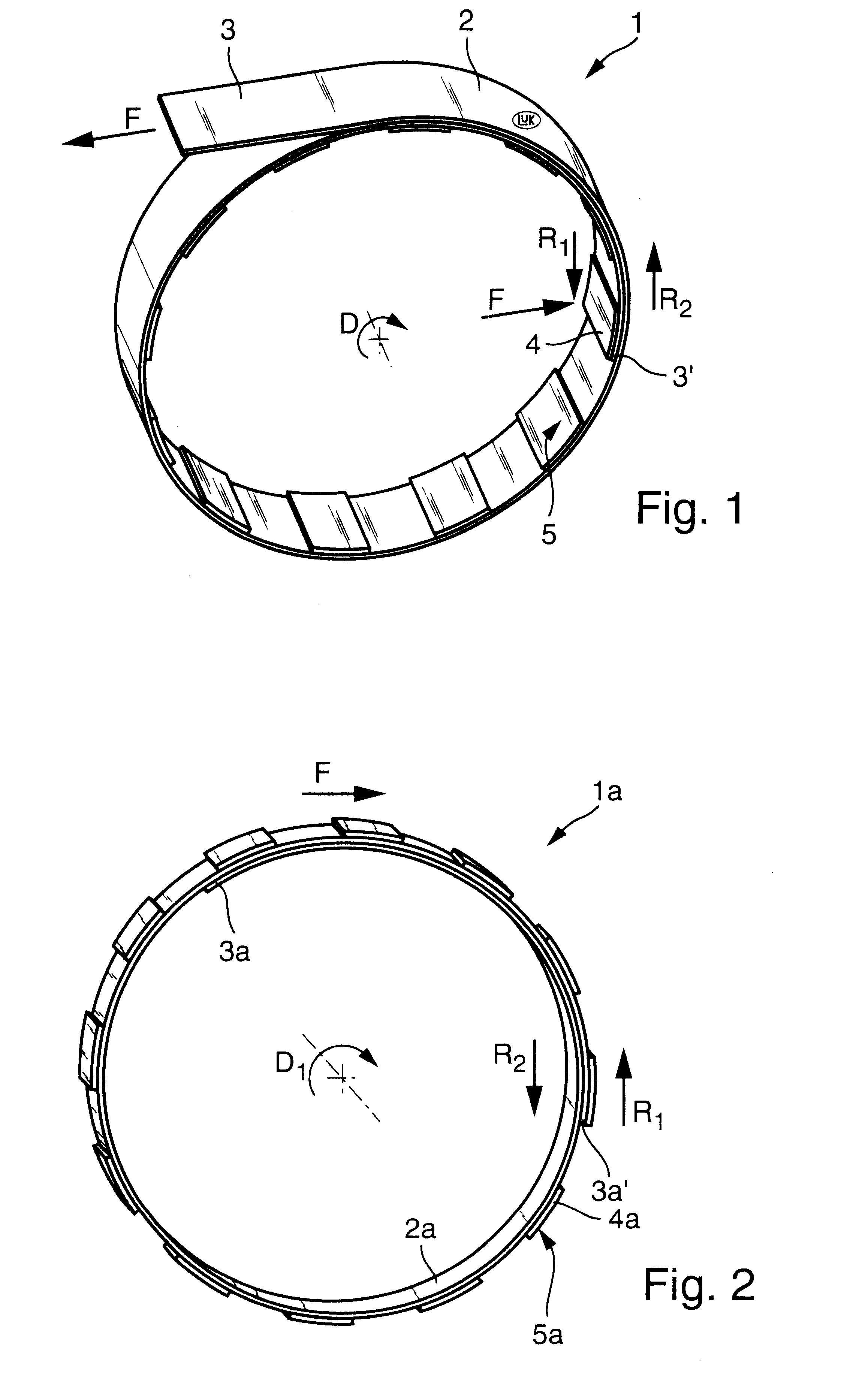
FIG. 1 shows a freewheel 1 which comprises a flexible band 2 (preferably a metallic band) wound around a cylindrical part, e.g., a shaft (not shown), in such a way that it forms a complete convolution or more than a complete convolution (e.g., at least two complete con-volutions). The illustrated band 2 has a length such that a median portion thereof overlies or overlaps the end portion 3' and that the other (outer) end portion 3 is offset relative to the end portion 3' by an angle of close to 180.degree.. The end portion 3 is affixed to a component part of the power train in which the freewheel 1 is put to use, e.g., to a component part which is stationary relative to the part (shaft) surrounded by the band 2. For example, the complementary component part can include or constitute a part of a housing or casing of a prime mover, the sun gear or wheel of a planetary transmission or the planet carrier or internal gear of such transmission.

If the band 2 contacts the peripheral surface ...


PUM


Abstract

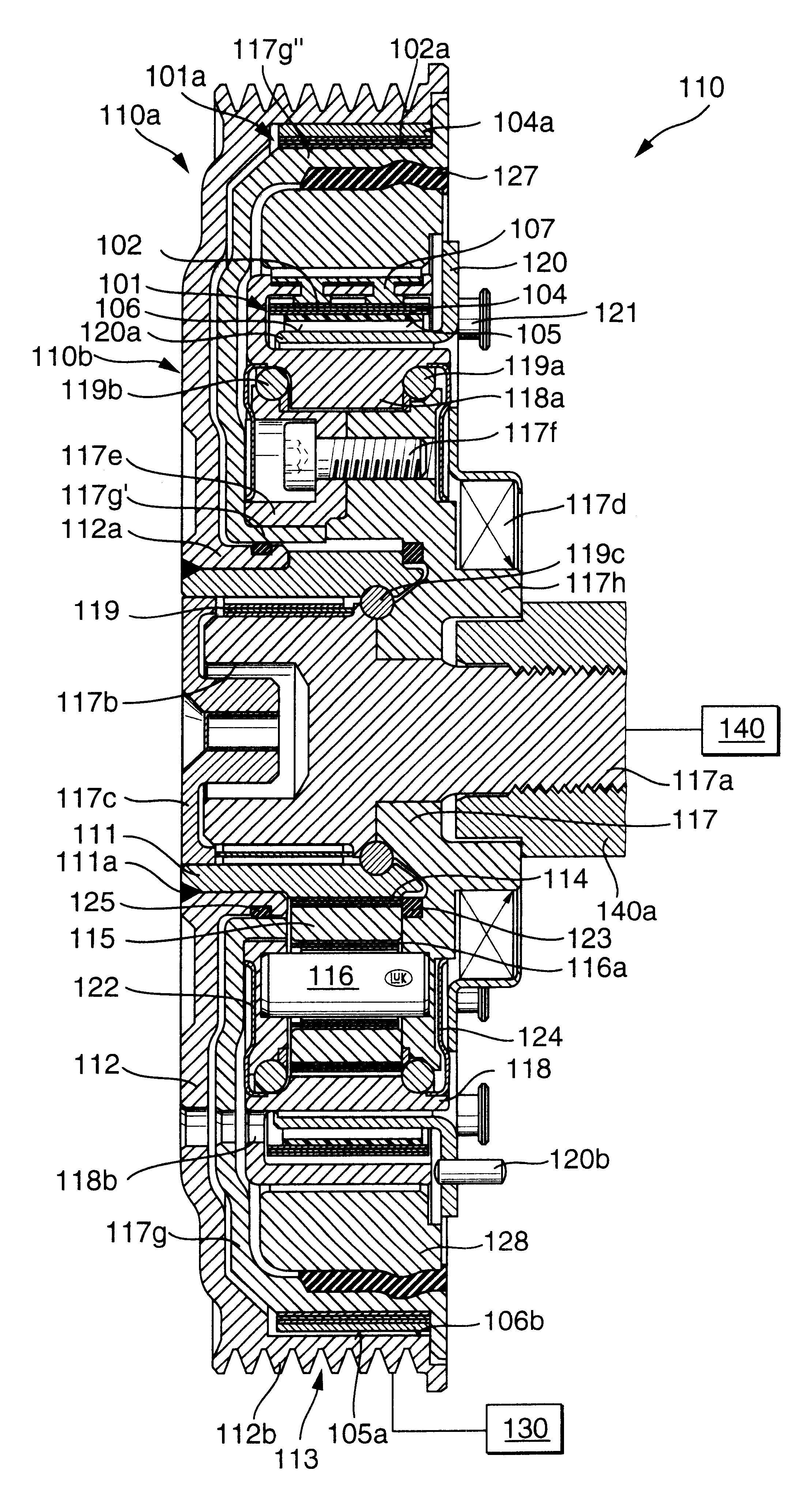
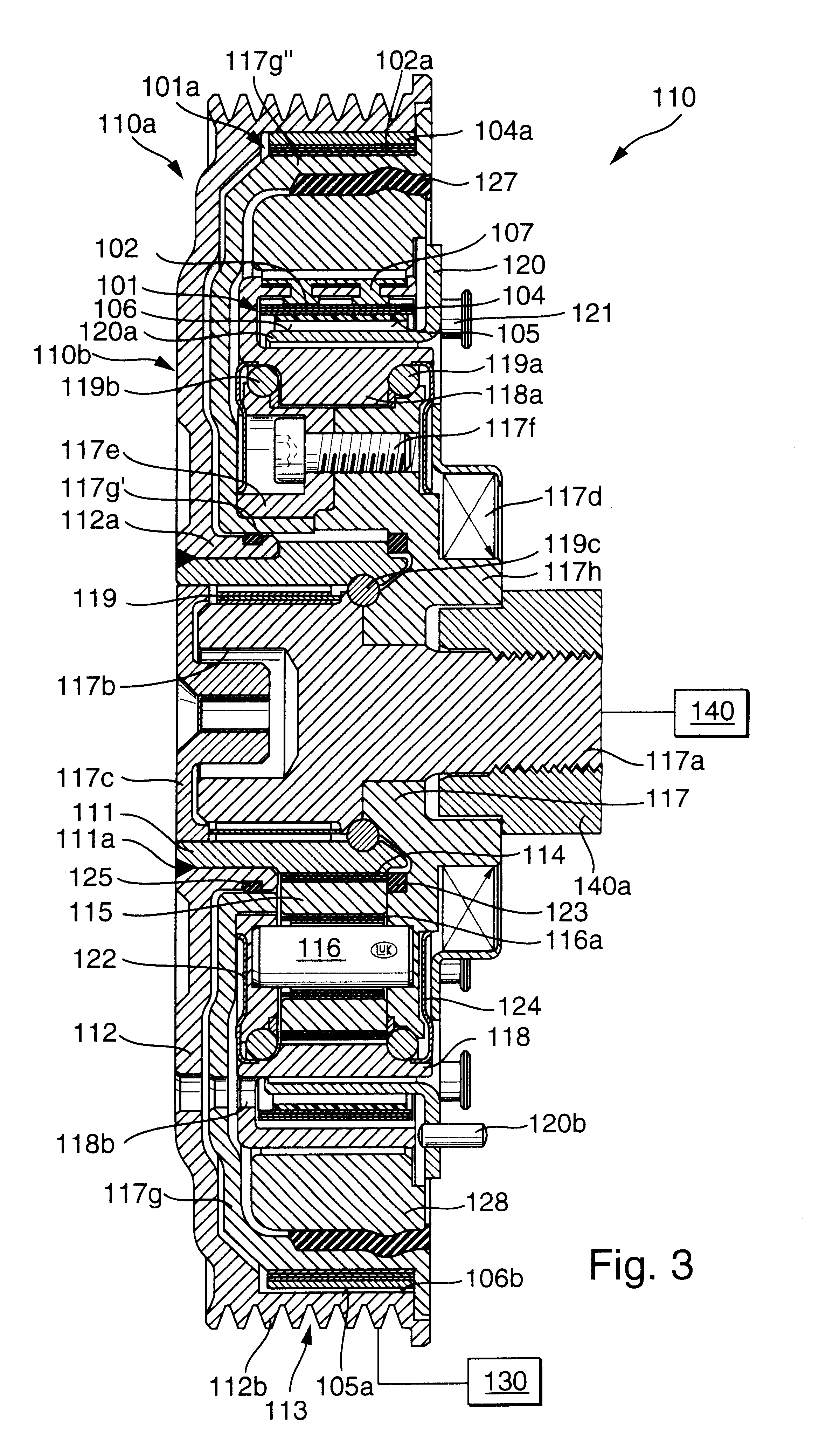
The power train of a motor vehicle has an engine which normally drives the wheels and can be started by an electric motor which acts as a generator once the engine is started. The torque transmitting connection between the crankshaft of the engine and a shaft of the motor includes a planetary and one or more freewheels of the type employing an elongated belt surrounding a rotary part and being surrounded by the internal surface of a hollow part. The belt or belts can be urged into or released from frictional engagement with one of the adjacent surfaces by centrifugal force and / or by an electromagnet.

Description

CROSS-REFERENCE TO RELATED CASESThis application claims the priority of the commonly owned copending German patent application Ser. No. 100 50 637.2 filed Oct. 12, 2000. The disclosure of the aforesaid priority application, as well as that of each U.S. and foreign patent and / or patent application identified in the specification of the present application, is incorporated herein by reference.The present invention relates to improvements in power trains, especially in power trains which can be utilized in motor vehicles, and more particularly to improvements in torque transmitting arrangements which can be utilized in a power train for controlled transmission of torque between a driving unit and a driven unit, e.g., between a first machine (such as a combustion engine) and a second machine (such as an electrical machine which can serve as a motor or as a generator). Still more particularly, the instant invention relates to improvements in power trains of the type capable of automatica...

Claims


Application Information

Patent Timeline
Patent Type & Authority Patents(United States)
IPC IPC(8): B60K6/00B60K6/04F02N15/02F16G1/20F16G1/22F16H57/10F16H55/36F16D43/16F16H3/00F16D43/00F16H57/00F16D27/00F16G1/00F16H3/54F16H63/30F16H3/44B60K6/365B60K6/383B60K6/40B60K6/48F16D41/20F16H31/00F16H57/08
CPCB60K6/365B60K6/40B60K6/48F02N15/026F16D28/00F16D43/16F16G1/20F16G1/22F16H3/005F16H55/36F16H57/10B60K6/383Y10S903/913F16H3/54F16H63/3003Y02T10/6221Y10S903/951Y10S903/91B60K2006/268Y02T10/62
Inventor MAN, LASZLODAIKELER, RENE
Owner LUK LAMELLEN & KUPPLUNGSBAU BETEILIGUNGS KG
Learn More