Focus jump device for reproducing information from a storage medium

a technology of information and storage media, applied in the direction of data recording, recording head arrangement, instruments, etc., can solve the problems of deterioration of performance, unstable control, and easy external disturbance of open control of feed-forward typ

Inactive Publication Date: 2003-06-24
PIONEER CORP
View PDF8 Cites 54 Cited by
  • Summary
  • Abstract
  • Description
  • Claims
  • Application Information

AI Technical Summary

Problems solved by technology

However, the open control of the feed-forward type is susceptible to external disturbance.
For example, the control may be unstable due to the vibration of the disc surface at the time of the focus jump, or variation of the interlayer spacing.
Further, the servo may not be quickly set at the time of closing the focus servo after the focus jump, or the focus servo may lose control, thus leading to the deterioration of performance.
Therefore, the focus error signal should be referred to at any positions in all three areas AREA1, AREA2 and AREA3, and hence the feedback control is difficult perform with using such a non-linear signal.
In addition, since the polarity of the focus error signal reverses within the AREA2 as shown in FIG. 5B, the performance of the feedback loop is disturbed.
In addition, as shown in FIG. 2, the frequency band of the focus jump is sufficient

Method used


Image

  • Focus jump device for reproducing information from a storage medium
  • Focus jump device for reproducing information from a storage medium
  • Focus jump device for reproducing information from a storage medium

Examples


first embodiment

Next, an experimental example will be described with reference to FIGS. 17 and 18. FIG. 17 is a block diagram showing a configuration of the focus jump device employed in this experimental example. It is noted that the function of the device is achieved by the execution of predetermined programs by the DSP, except for the actuator 10, the driver 11, the photodetector 22, the decoder 20 and the CPU 21.

In FIG. 17, the actuator 16 has a movable portion for carrying an object lens and a supporting portion for supporting the movable portion by a spring or the like. The actuator 10 moves the movable portion toward the disc from its lower side in the vertical direction in response to the drive signal supplied from the driver 11. The driver 11 generates the drive signal in response to the input signal. The adder 12 adds the phase-compensated signal outputted from the stabilizing compensator 15 to the feedforward signal outputted from the feedforward compensator 18, and supplies the resulta...

2nd embodiment

[2] 2nd Embodiment

Next, the second embodiment of the present invention will be described with reference to FIGS. 24 and 25. It is noted that the components identical to those in the first embodiment will be represented by identical reference numerals and the description therefore will be omitted.

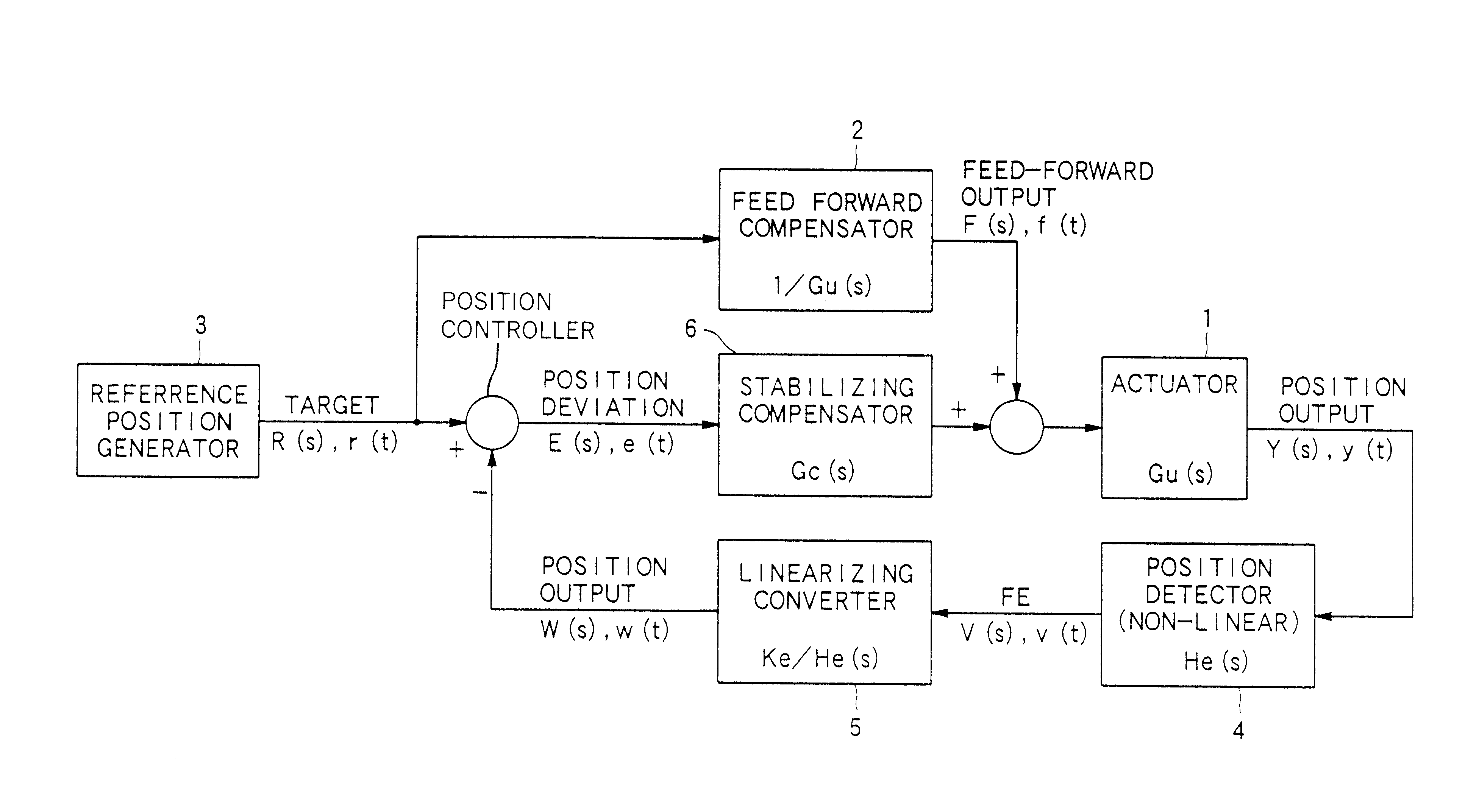
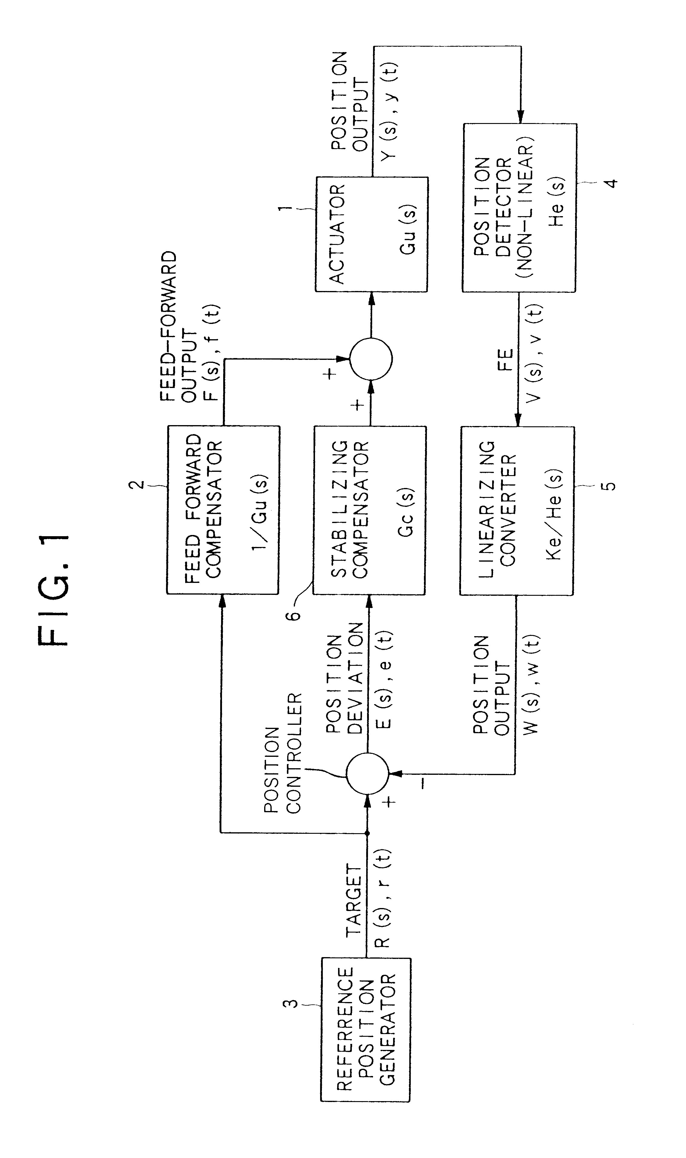
In the first embodiment, the focus error signal is compared with a profile having linear areas after the focus error signal is linearized. The focus jump device of the second embodiment is different from the first embodiment in that the non-linearity of the focus error signal is considered and non-linear target value is given. FIG. 24 is a block diagram showing the schematic configuration of the focus jump device of the second embodiment. The components that are identical to those shown in FIG. 1 are applied with the identical reference numerals and the description will be omitted.

As shown in FIG. 24, in the focus jump device of the second embodiment, the focus error signal outputted by the ...


PUM


Abstract

A focus jump moves a focus position of a light beam in a direction perpendicular to the storage medium to the focus position corresponding to a target recording layer so that the light beam is irradiated on the target recording layer. The device includes: a focus position moving unit for moving the focus position of the light beam; a focus error signal detector for detecting a focus error signal based on a variation of a returning light from the storage medium; a feedforward controller for supplying a drive signal to the focus position moving unit to move the focus position of the light beam in an acceleration state in an acceleration control and to move the focus position of the light beam in a deceleration state in a deceleration control; and a position controller for comparing the focus error signal, detected the time of movement of the focus position of the light beam to the target recording layer, with a predetermined target value to generate an error, and for feeding back the drive signal to the focus position moving-unit to reduce the error thereby to control the focus position of the light beam.

Description

1. Field of the InventionThe present invention relates to a focus jump device for jumping between recording layers in a storage medium, such as an optical disc, having at least two recording layers.2. Description of Related ArtIn a conventional optical disc reproduction apparatus such as a Compact Disc player, a focus servo control is performed as follows. First, a predetermined drive signal of a sawtooth waveform, for example, is supplied to a drive circuit of an actuator, and then the drive circuit applies an output corresponding to the drive signal to a focus coil provided in the actuator. Thus, the actuator moves toward or away from the disc. Then, a laser beam is irradiated on the optical disc by the objective lens of the actuator, and the light reflected by the optical disc is converted into an electric signal by the photodetector to produce a focus error signal. The focus error signal has a zero-level output when the relative distance between the objective lens and the disc i...

Claims


Application Information

Patent Timeline
IPC IPC(8): G11B7/085G11B7/00G11B7/09
CPCG11B7/08511G11B2007/0013
Inventor TATEISHI, KIYOSHITAKAHASHI, KAZUO
Owner PIONEER CORP
Why Eureka
Try Eureka