Method for making steel with electric arc furnace

a technology of electric arc furnace and steelmaking, which is applied in the field of steelmaking, can solve the problems of increasing electrode erosion, affecting and causing co and nox to rise, etc., and achieves the effects of reducing the natural gas or propane rate through the burner, reducing the oxygen rate, and reducing the efficiency of process improvemen

Inactive Publication Date: 2003-06-24
NUCOR CORP
View PDF11 Cites 7 Cited by
  • Summary
  • Abstract
  • Description
  • Claims
  • Application Information

AI Technical Summary

Benefits of technology

In more modern EAF furnaces, oxygen lancing has been done through the oxy-fuel burners by simply increasing the oxygen rates and decreasing the natural gas or propane rates through the burners. In any case, melting and refining of the steel during the campaign with the use of separate oxygen lances, or oxygen lancing through the oxy-fuel burners, can be highly efficient. However, such oxygen lancing of any type can negatively impact on productivity, can accelerate electrode erosion, and can have a detrimental effect on the electrodes. Further, oxygen lancing can create unacceptable levels of CO and NOX that must be consumed or otherwise disposed of in the offgas system.
Oxygen lancing takes advantage of exothermic reactions in oxidizing of carbon and iron in the steel melt creating CO and FeO, and in stirring of the molten steel resulting in temperature and composition homogeneity through the molten steel bath. When used for scrap cutting, the oxidation reaction is primarily with the iron resulting in high energy input as iron is reacted to produce FeO. However, this reaction has had a direct negative impact on yield, and therefore high oxygen rates have not been usually used during cut-in of the scrap. Later in the campaign, when a molten pool is formed, the FeO is reduced out of the slag by carbon in the bath. Thus, the net effect is to produce large amounts of CO gas from the oxygen that is injected by lancing.
The oxygen rate during lancing must therefore be controlled so as not to create excessive yield losses and generate high levels of CO that must be captured in the DES system and in unacceptable ambient levels in the work environment. Typically up to 10% of the CO not oxidized in the furnace is exhausted through the secondary fume capture system during meltdown of the steel. Moreover, the major drawback in high oxygen lance rates is the effect on fume system controls and the production of NOX. All of this must be taken into account in controlling and varying oxygen lance rates during the campaign, and balancing the natural gas or propane levels with the oxygen rates where the oxygen lancing and the oxy-fuel burning is done through the same orifices.
Furthermore, the carbon that reacts with the oxygen to form CO in the molten steel bath can be from the electrodes, increasing electrode erosion and melting costs. Typically carbon is injected into the bath to provide for decarbonization of the molten steel, but also to protect electrodes from such erosion. If in addition, the stirring effect of the oxygen lancing brings bath carbon or injected carbon into contact with the FeO in the slag, an even greater quantity of CO can be produced.
The carbon injection must be controlled for this purpose, as well as to cause foaming of the slag. The foaming of the slag has great benefits in operation of the electric arc furnace in greatly reducing heat loss to the side walls of the furnace, and channelling heat transfer from the electric arcs to the molten steel thereby providing for higher rates of energy input, reduced power and voltage fluctuations, reduced electrical and audible noise, and increased arc length without increasing heat loss, electrode consumption, or refractory consumption.
There is needed, therefore, a simple and efficient system for coordinating the operation of the oxy-fuel burning, oxygen lancing, carbon injection, and electrical current input so as to provide high productivity steelmaking in the EAF. The present invention provides just such a system.

Problems solved by technology

The problem is that each of these energy input systems is efficient for transferring heat in different parts of the campaign, but each must also be controlled to inhibit detrimental interaction between the electrodes, the oxy-fuel burners, and the oxygen lances (as well as to avoid any loss of production or losses of yield efficiency).
However, such oxygen lancing of any type can negatively impact on productivity, can accelerate electrode erosion, and can have a detrimental effect on the electrodes.
Further, oxygen lancing can create unacceptable levels of CO and NOX that must be consumed or otherwise disposed of in the offgas system.
However, this reaction has had a direct negative impact on yield, and therefore high oxygen rates have not been usually used during cut-in of the scrap.
Moreover, the major drawback in high oxygen lance rates is the effect on fume system controls and the production of NOX.
Furthermore, the carbon that reacts with the oxygen to form CO in the molten steel bath can be from the electrodes, increasing electrode erosion and melting costs.

Method used


Image

  • Method for making steel with electric arc furnace
  • Method for making steel with electric arc furnace
  • Method for making steel with electric arc furnace

Examples


Embodiment Construction

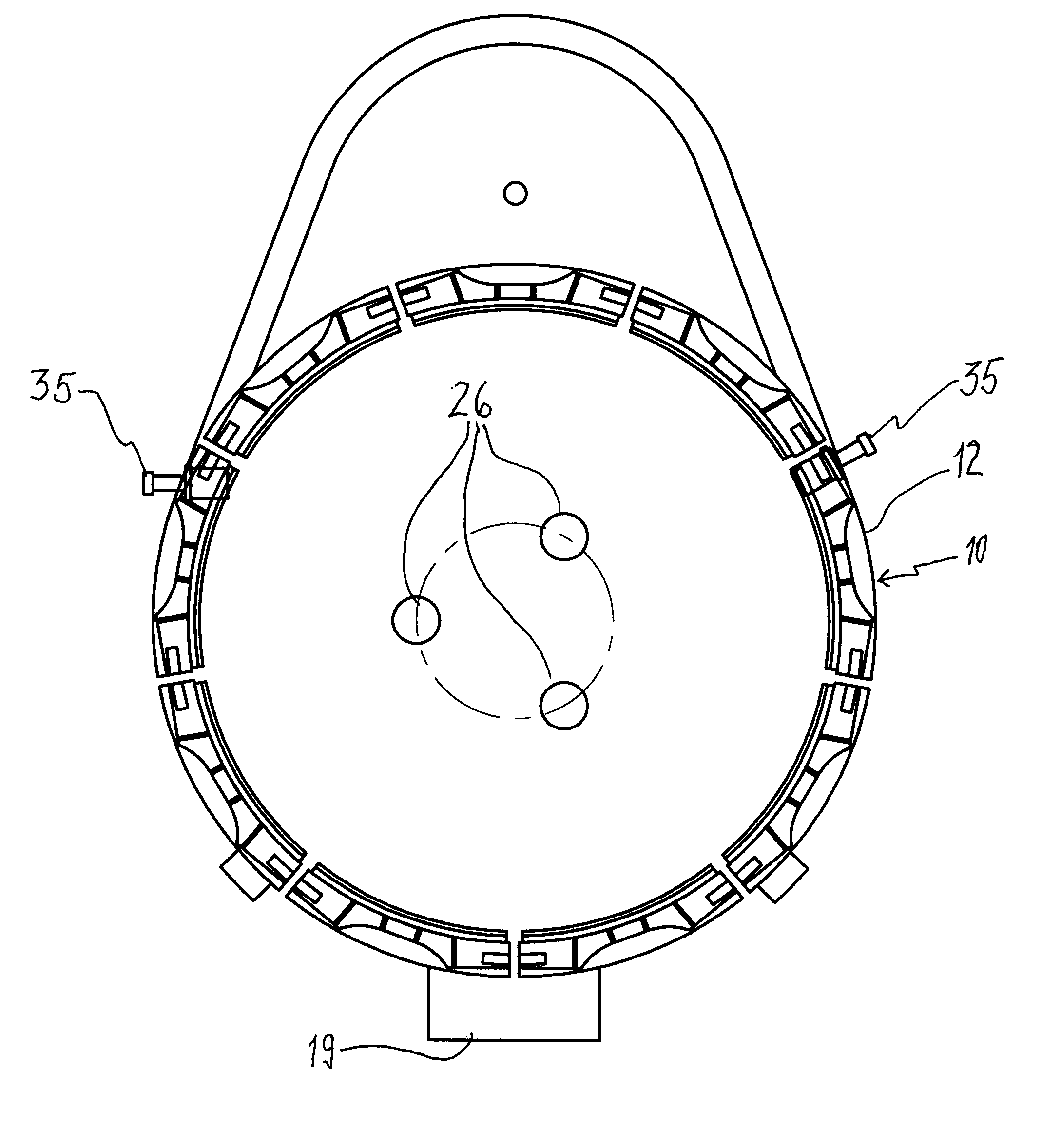
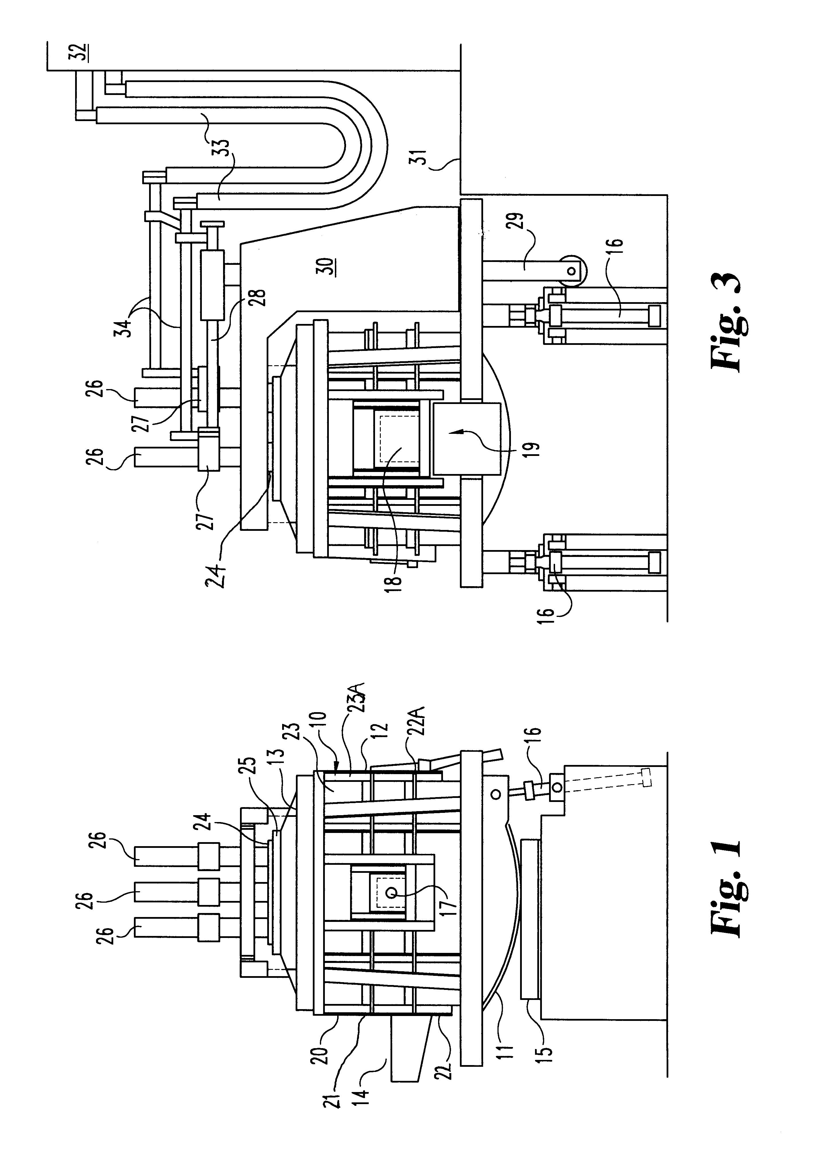
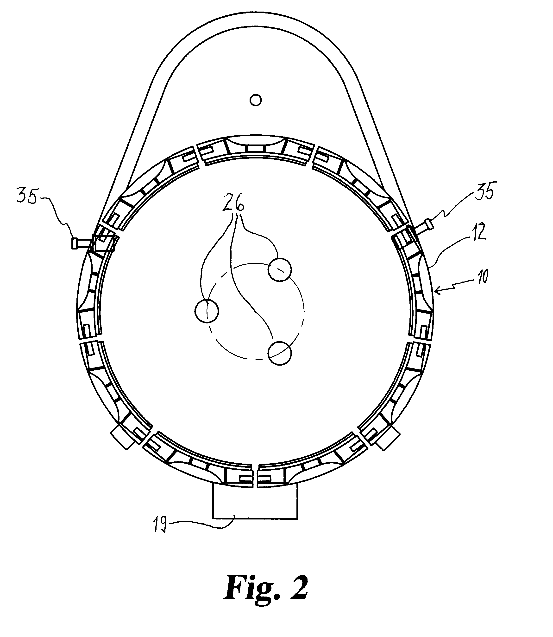
Electric arc furnace (EAF) 10 is generally cylindrical in shape, and has a generally spherical shaped bottom 11, sidewalls 12 and a roof 13. Although described above with reference to an AC EAF furnace, the invention may also be used with a DC EAF furnace. In either case, the bottom 11 is refractory lined, and the sidewalls 12 are generally refractory lined to above the slag line. The EAF also has a taphole / spout 14. The EAF rests on a rocker rail 15, and is capable of being tilted by hydraulic cylinders 16 to discharge the molten metal from the furnace through spout 14.

Also, provided in sidewall 12 is slide door 17 for charging and a backdoor 18 with a slag apron 19 for discharge of the slag from the furnace. The electric arc furnace 10 may have a split shell with a top portion 21 capable of being quickly decoupled and removed from a bottom portion 22. This facilitates and minimizes downtime due to change out of the top portion 21 of the furnace, and provides for rapid relining of ...


PUM

PropertyMeasurementUnit
voltageaaaaaaaaaa
electrical currentaaaaaaaaaa
currentaaaaaaaaaa

Abstract

A method of making steel in an electric arc furnace is provided. The method comprises the steps of measuring electrical current in at least two phases of electrical power supplied to electrodes in the furnace during a campaign, establishing a setpoint current level and an input time interval, and switching between modes of inputting exothermic energy into the steel melt when at least two phases have measured current levels below the setpoint for the input time interval.

Description

BACKGROUND & SUMMARYThis invention relates to steelmaking and particularly to the making of steel by electric arc furnace (EAF).The electric arc furnace has evolved considerably with the use of exothermic reactions to complement the electric arc for scrap melting and steel refining. The exothermic reactions have come in two (2) forms: direct oxygen injection using oxygen lances, and the use of oxy-fuel burners. The problem is that each of these energy input systems is efficient for transferring heat in different parts of the campaign, but each must also be controlled to inhibit detrimental interaction between the electrodes, the oxy-fuel burners, and the oxygen lances (as well as to avoid any loss of production or losses of yield efficiency).Oxy-fuel burners are common equipment in electric arc furnaces. Typically such burners are located in either the slag door or side wall of the EAF. The oxy-fuel burners are very efficient in heat transfer to the scrap at the start of the melt-in...

Claims


Application Information

Patent Timeline
Patent Type & Authority Patents(United States)
IPC IPC(8): H05B7/148H05B7/00
CPCH05B7/148Y02P10/25
Inventor DUNN, THOMAS MICHAELNISSEN, ERIK RENE OCKLIND
Owner NUCOR CORP
Why Eureka
Try Eureka