Gusset plates connection of beam to column

a technology of gusset plates and beams, applied in the direction of parkings, portal frames, buildings, etc., can solve the problems of unsuitable resistance, uncertain welding practice of beam flanges directly to the column, fractured welds, etc., to increase the load-carrying capacity of steel frame structures, increase lateral and vertical load-carrying capacity, and increase the effect of load-carrying stability and capability

Inactive Publication Date: 2003-07-15
MITEK HLDG INC
View PDF21 Cites 81 Cited by
  • Summary
  • Abstract
  • Description
  • Claims
  • Application Information

AI Technical Summary

Benefits of technology

This invention increases both the lateral and vertical, load-carrying stability and capability of the steel frame structure. The invention herein provides such capability, providing both a lateral and vertical load moment-resisting connection and increased vertical load-carrying capability. Further, this invention complies with the industry's current steel moment-resisting frame guidelines contained in Federal Emergency Management Agency (FEMA) guidelines (FEMA publications 350 and 351).
Consequently, the improved design of the invention is capable of carrying greater loads and capable of withstanding greater earthquakes and other calamities which may place extreme strain on a structure.
The beam-to-column connection invention herein may be made in the shop under controlled conditions and placed in new constructions or constructed in the field for new or retrofit constructions. Shop fabrication provides for better quality construction of a beam-to-column connection by reason of better control of the welding process and easier access to and handling of all parts of the connection. The invention effectively makes use of fillet welds, as well as full-penetration, partial-penetration groove welds, flare-bevel groove welds and any other suitable welds, all of which are better made under shop conditions, although they can suitably be made in the field, at greater expense and likely with less quality. Beam splices can be used in the field for erection purposes. Such splice connections when used are commonly located at structural points of reduced flexural stress. That is, the splice connections are located at some distance from the beam-to-column connection.

Problems solved by technology

Experience has shown that the practice of welding the beam's flanges directly to the column is uncertain and / or unsuitable for resistance to earthquakes, explosions, tornadoes and other disastrous events.
Such connection means and welding practice has resulted in sudden, fractured welds, the pulling of divots from the face of the column flange, cracks in the column flange and column web, and various other failures.
Such highly-restrained welds do not provide a reliable mechanism for dissipation of earthquake energy, or other large forces, and can lead to brittle fracture of the weld and the column, particularly the flange of the column and the web of the column in the locality of the beam-to-column joint, (known as the "panel zone").
That is, the beam-to-column moment-resisting connections in a steel frame building, in an earthquake, are subjected to large rotational demands in the vertical plane due to interstory lateral building drift.

Method used


Image

  • Gusset plates connection of beam to column
  • Gusset plates connection of beam to column
  • Gusset plates connection of beam to column

Examples


Embodiment Construction

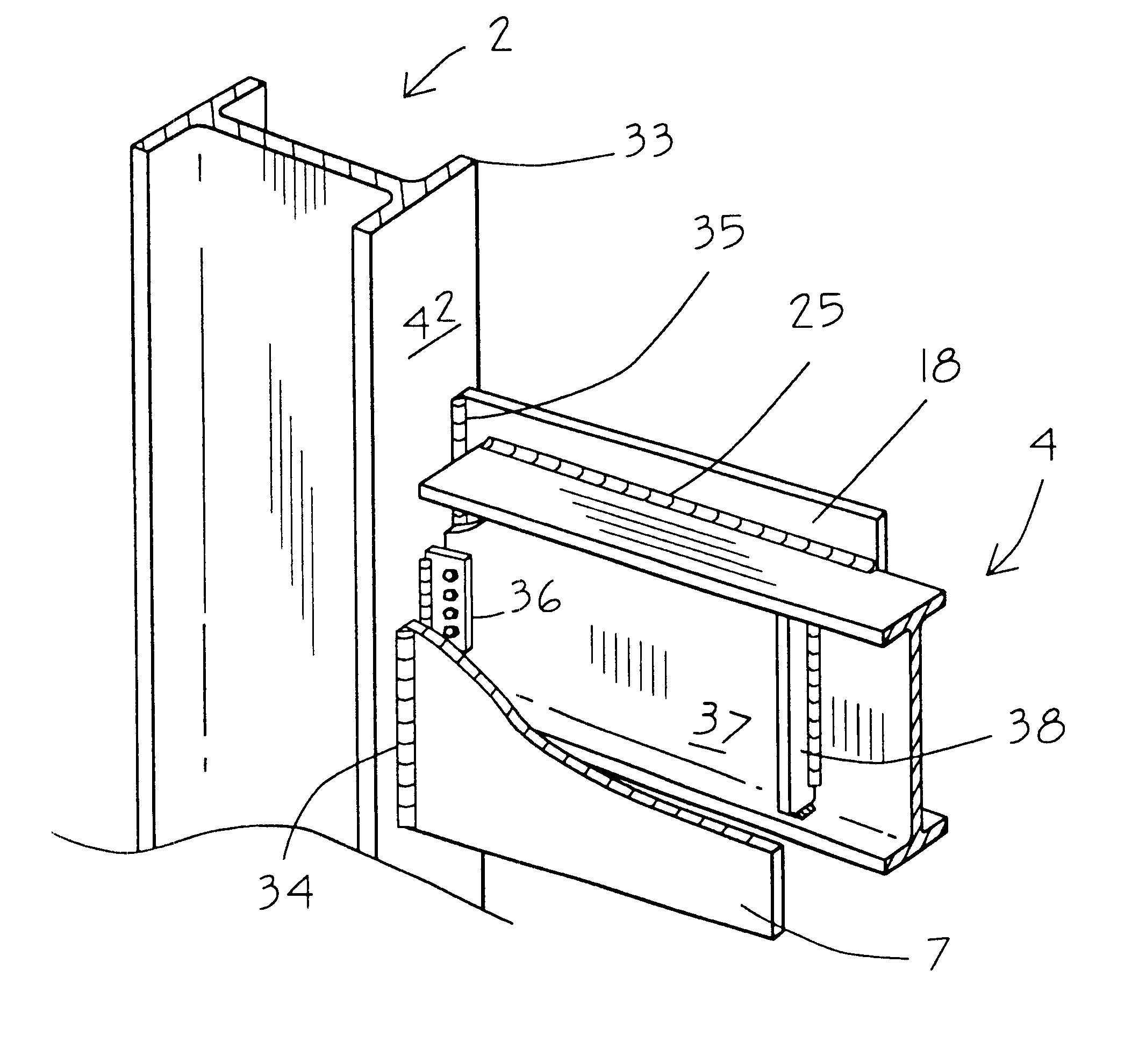
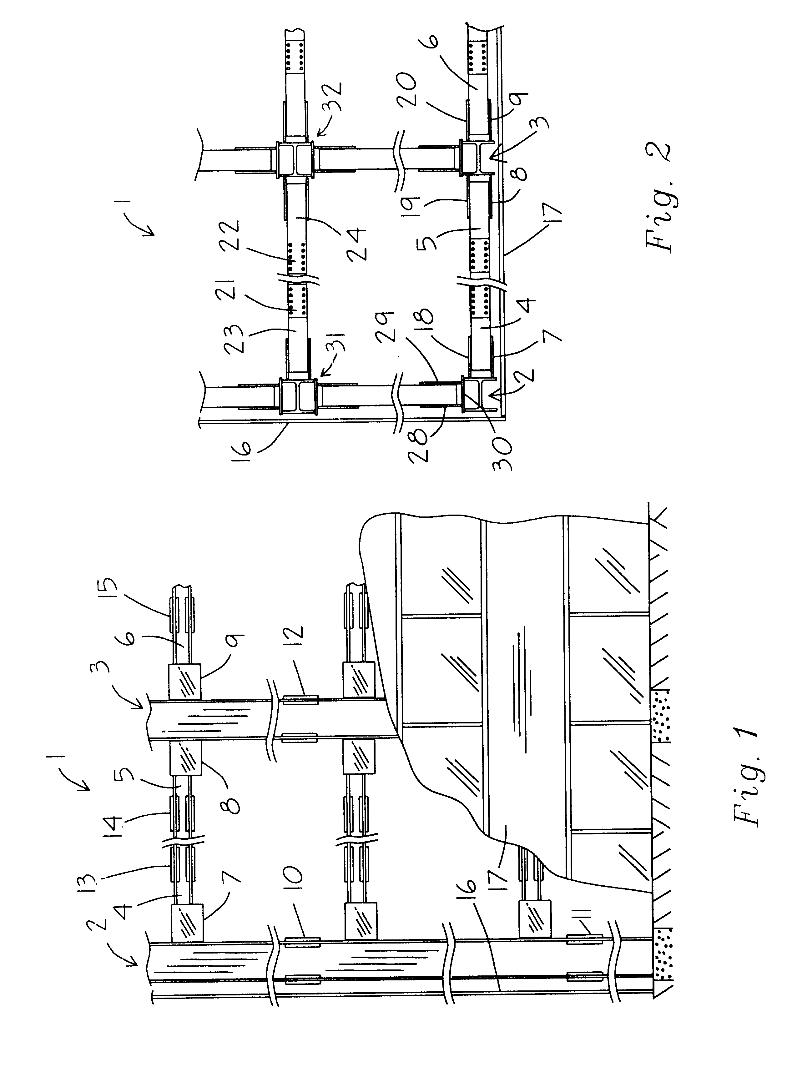
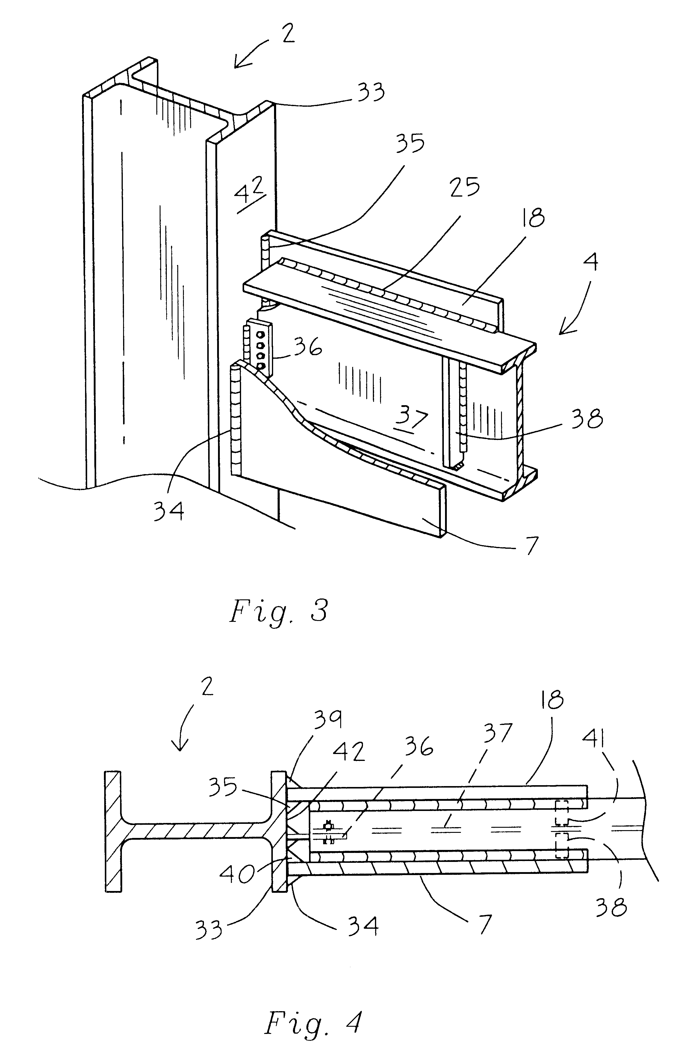
Referring to FIG. 1, there is shown the framework 1 for a moment-resisting building, tower or other structure requiring "primary support" structure. Such "primary support" structure is comprised of columns 2 and 3 and beam sections 4, 5 and 6 and the like. The beam sections 4, 5 and 6 are connected to the columns 2 and 3 through the use of gusset plates 7, 8 and 9. Columns 2 and 3 are spliced together through the use of splice plates 10, 11 and 12, or, alternatively, spliced through full-penetration or partial-penetration groove welds or any other suitable welds. Beam sections 4, 5 and 6 may be spliced together, as shown, through the use of splice plates 13, 14 and 15, or, alternatively, they may be spliced using full-penetration or partial-penetration groove welds or any other suitable welds.

Of course, a single long beam may be used in place of spliced beam sections. So, too, the columns may be constructed in long sections.

Curtain wall 16, shown in elevation, and curtain wall 17, s...


PUM


Abstract

This invention relates to columnar, "primary support" for a building or other heavy structure, in which a beam is connected to a column in a strong, moment-resisting connection comprised of two gusset plates welded to a flange or the face of the flange of the column and welded to the beam or attached to cover plates fixedly attached to the beam.

Description

BACKGROUND OF THE INVENTIONIt has been found in a moment-resisting building having a structural steel framework, that most of the energy of an earthquake, or other extreme loading condition, is absorbed and dissipated, in or near the beam-to-column joints of the building.In the structural steel construction of moment-resisting buildings, towers, and similar structures, most commonly in the past, the flanges of beams were welded to the face of columns by full-penetration, single bevel, groove welds. Thus, the joint connection was comprised of highly-restrained welds connecting a beam between successive columns. Vertical loads, that is, the weight of the floors and loads superimposed on the floors, were and still are assumed by many to be carried by vertical shear tabs or pairs of vertical, structural angle irons arranged back-to-back, bolted or welded to the flange of the beam and bolted or welded to the face of the column.In the prior art, the greater part of the vertical load place...

Claims


Application Information

Patent Timeline
Patent Type & Authority Patents(United States)
IPC IPC(8): E04B1/24E04C3/32E04C3/30E04C3/38E04C3/40
CPCE04B1/2403E04C3/32E04C3/40E04B2001/2415E04B2001/2442E04B2001/2445E04B2001/2448
Inventor HOUGHTON, DAVID L.
Owner MITEK HLDG INC
Why Eureka
Try Eureka