

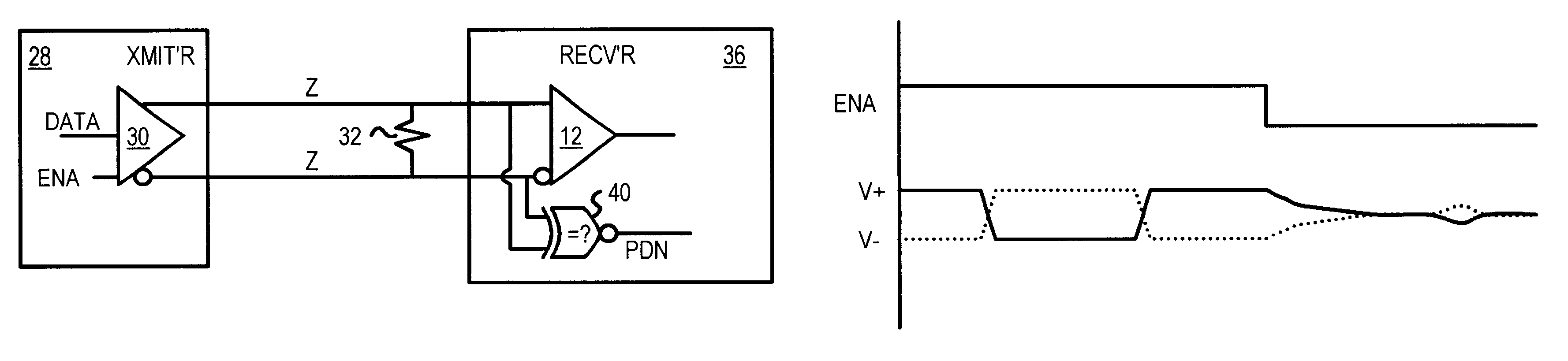
Power down mode signaled by differential transmitter's high-Z state detected by receiver sensing same voltage on differential lines
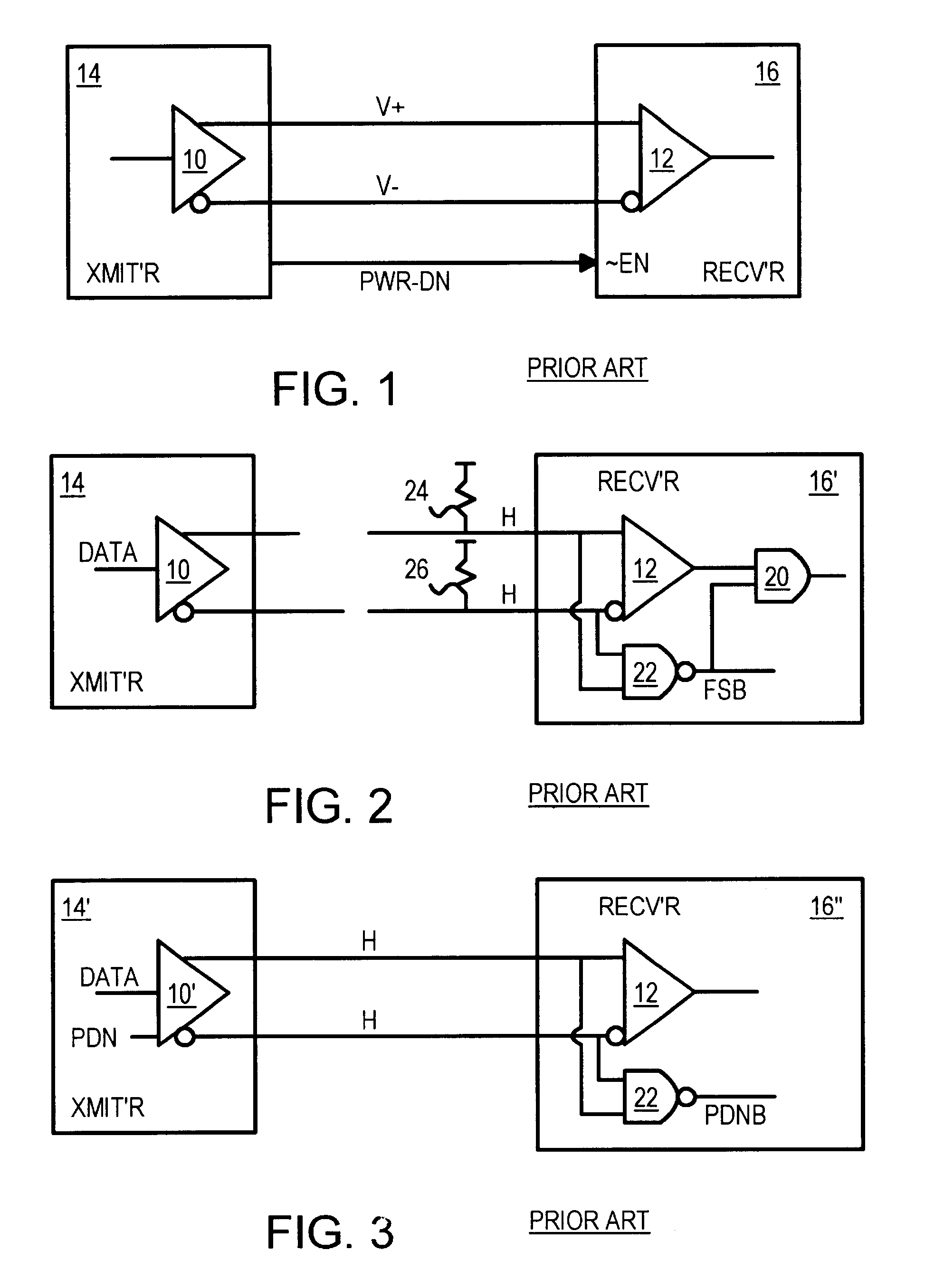
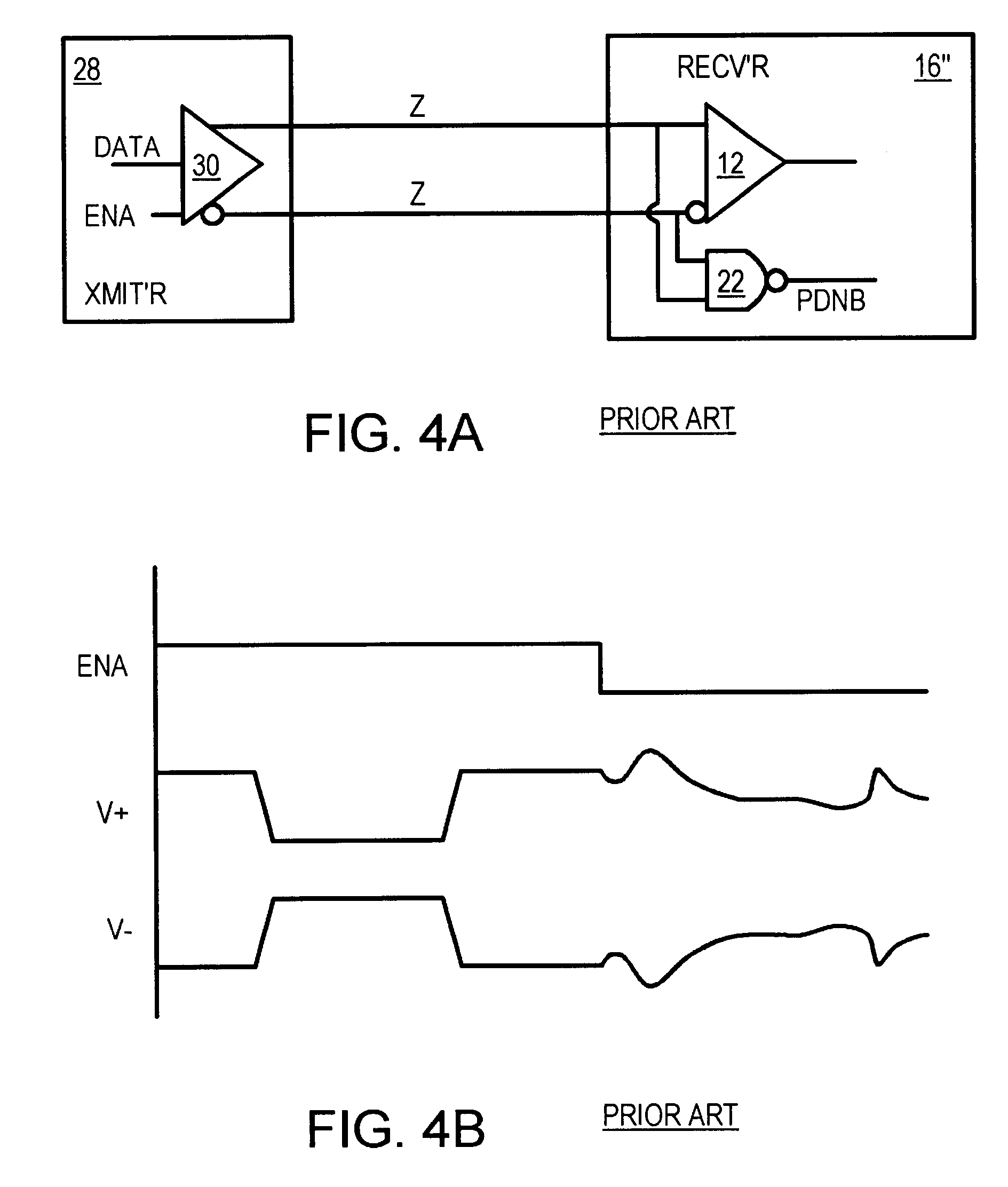
a technology of differential transmitter and receiver, which is applied in the direction of pulse manipulation, pulse technique, instruments, etc., can solve the problems of abnormal or illegal high-high condition, system not in continuous use, and limited number of available pins on the integrated circuit chip
- Summary
- Abstract
- Description
- Claims
- Application Information
AI Technical Summary
Problems solved by technology
Method used
Image

Examples
Embodiment Construction
Several other embodiments are contemplated by the inventor. For example other devices such as additional gates, inverters, buffers, resistors, and capacitors can be added. Many other applications besides memory module power-down are possible, such as for network cards, wireless subsystems, display systems, etc., in PC or other systems.
The power-down signal may be driven off the receiver chip to other chips such as memory chips on a memory module. The equal-voltage detector could be integrated with the differential receiver and the circuits to be powered down, or it could be separate from either or both of the differential receiver and the powered-down circuits. Signals can be active high or active low and can be inverted and logic re-arranged using DeMorgan's theorem. The detection circuits can be flipped over with n-channel and p-channel devices reversed. Other equal-voltage detectors could be substituted, and the ones described can be modified in a variety of ways. Pull-down or pu...
PUM
 Abstract
Description
Claims
Application Information