Hydrodynamic coupling device

a technology of coupling device and hydraulic pump, which is applied in the direction of fluid gearing, rotary clutch, liquid fuel engine components, etc., can solve the problems of affecting the flow circuit, requiring more material use, thicker material deformation, and acquiring a markedly higher mass moment of inertia

Inactive Publication Date: 2003-07-22
ZF FRIEDRICHSHAFEN AG
View PDF4 Cites 9 Cited by
  • Summary
  • Abstract
  • Description
  • Claims
  • Application Information

AI Technical Summary

Benefits of technology

is to provide a hydrodynamic coupling device in which deformation of the turbine wheel due to axial shearing forces introduced during rotary operation can be avoided without adversely affecting the overall operation even though the turbine wheel has a large form of construction in the radial direction.
In the hydrodynamic coupling device according to the present invention, measures are taken to increase the rigidity of the turbine wheel in that region of the turbine wheel which is critical with regard to deformation when axial shearing forces are generated. Since other radial regions such as the region in which the turbine wheel shell carries the turbine wheel blades are not appreciably influenced by these measures, the operating characteristics of a coupling device of this type remains essentially uninfluenced by the provision of the reinforcing arrangement. That is, the turbine wheel shell which is generally produced as a sheet-metal molding may be manufactured with relatively thin sheet-metal material. The region in which the turbine wheel shell carries the turbine wheel blades is already reinforced by the fixed coupling of the turbine shell to the blades. The region in which the turbine wheel shell bridges a relatively large radial clearance is additionally protected against undesirable deformation by the provision of the reinforcing arrangement.
At least one reinforcing element does not contact, at least in regions, the connecting portion of the turbine wheel shell between a radially outer connecting region and a radially inner connecting region so that the reinforcing effect introduced by the reinforcing arrangement according to the present invention or the at least one reinforcing element may be provided as efficiently as possible. A hollow reinforcing structure is thus ultimately provided which can efficiently counteract the deformation forces occurring during rotary operation.
A configuration of this type may be provided by the turbine wheel shell being produced with an essentially U-shaped or V-shaped curvature profile between the radially outer connecting region and the radially inner connecting region. In addition to the increased rigidity in the axial direction introduced by the connecting arrangement according to the invention, a reinforcing effect in the radial direction may be obtained by the at least one reinforcing element extending essentially rectilinearly between a radially outer connecting region and a radially inner connecting region with the turbine wheel shell.
The reinforcing element may be an annular reinforcing element having a radially inner connecting region connected continuously in the circumferential direction to the turbine wheel shell and a radially outer connecting region connected continuously in the circumferential direction to the turbine wheel shell to obtain as efficient a reinforcement as possible with a simple structure.

Problems solved by technology

Axial forces generated in the fluid circuit induce a deformation of the turbine wheel shell in the large radial region of the connecting portion with the result that the turbine wheel moves axially away from the opposite pump wheel (and a guide wheel if the coupling device is a torque converter) and may thus cause disturbance in the flow circuit.
However, this not only has the disadvantage that more material has to be used and thicker material has to be deformed, but also the further considerable disadvantage that a markedly higher mass moment of inertia is acquired, this having an adverse effect on the overall operation of a device of this type.
Since other radial regions such as the region in which the turbine wheel shell carries the turbine wheel blades are not appreciably influenced by these measures, the operating characteristics of a coupling device of this type remains essentially uninfluenced by the provision of the reinforcing arrangement.

Method used


Image

  • Hydrodynamic coupling device
  • Hydrodynamic coupling device

Examples


Embodiment Construction

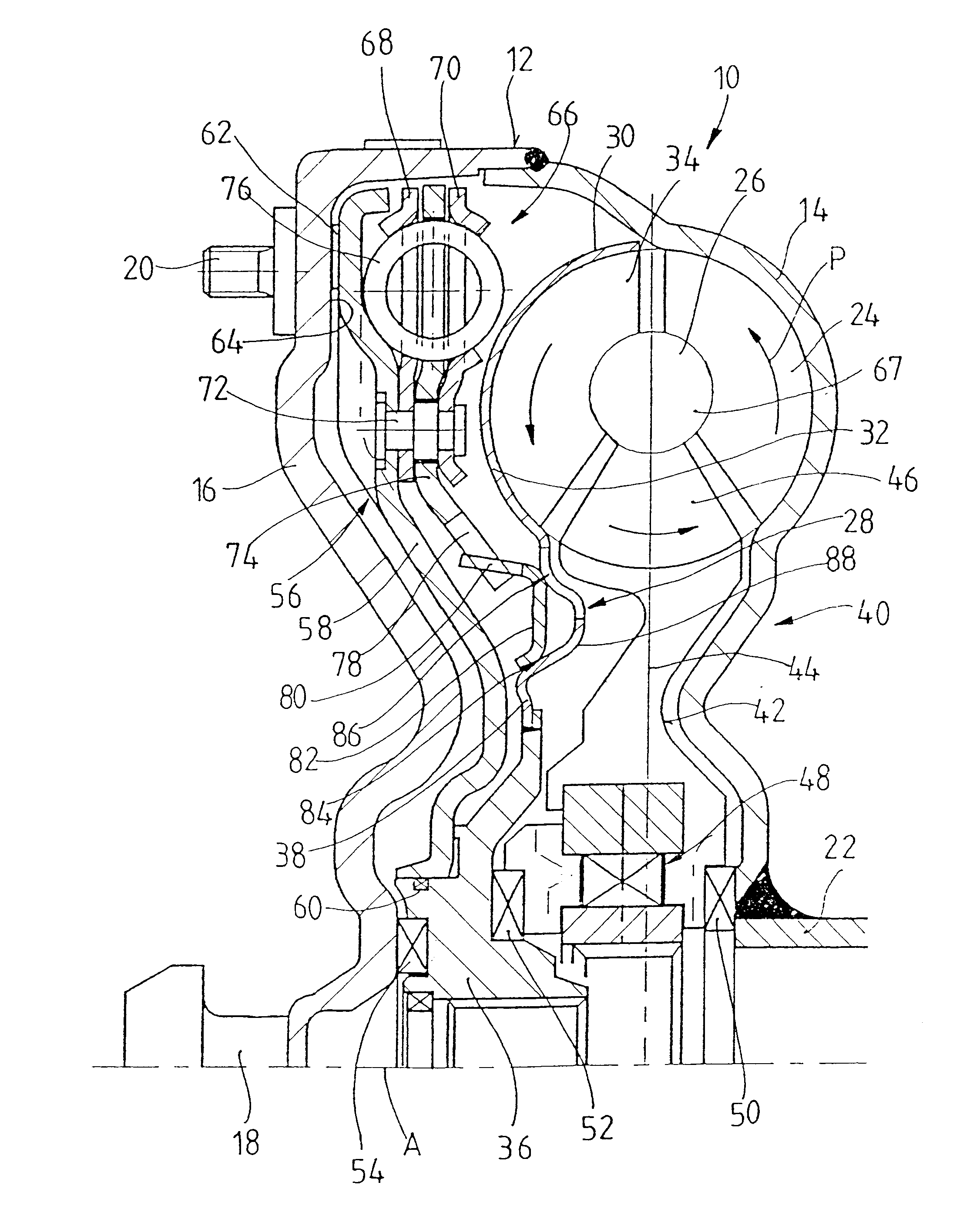
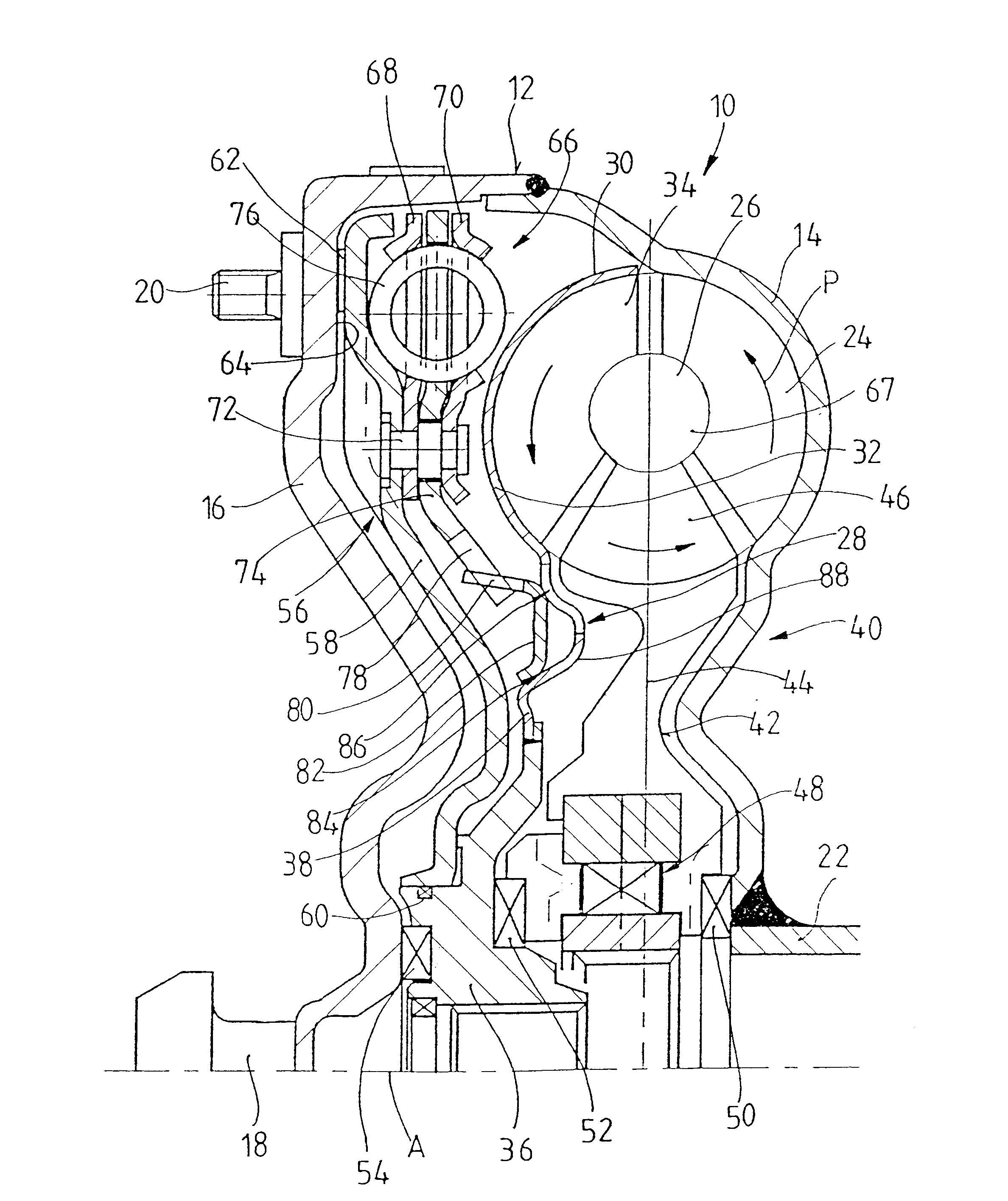
A hydrodynamic torque converter 10 according to the invention is shown in the FIGURE including a housing arrangement 12 with a pump wheel shell 14 and a housing cover 16 which are fixedly connected to one another at their radially outer sides such as, for example, by welding. A bearing journal 18 is carried on the radially inner region of the housing cover 16. The bearing journal 18 may be received, for example, in a bearing recess of a drive shaft, for example a crankshaft, for centering the torque converter 10 with respect to the drive shaft. A plurality of coupling elements 20 are arranged on the radially outer side of the housing cover 16. A radially outer side of a connecting member such as, for example, a flexible plate or the like, may be connected to the housing cover 16 via screws inserted in the coupling elements. Furthermore, the radially inner side of the connecting member may be fixedly connected to a drive shaft to make a rotationally fixed connection between the drive...


PUM


Abstract

A hydrodynamic coupling device includes a housing arrangement and a turbine wheel rotatably arranged in the housing arrangement for rotation about an axis of rotation. The turbine wheel has a turbine wheel shell carries a plurality of turbine wheel blades in its radially outer region and is connected to a turbine wheel hub in its radially inner region. The tubine wheel shell has a connecting portion connecting the radially outer region to the radially inner region. The turbine wheel shell further includes a reinforcing arrangement in its connecting portion.

Description

1. Field of the InventionThe present invention relates to a hydrodynamic coupling device such as a hydrodynamic torque converter including a housing arrangement and a turbine wheel rotatable in the housing arrangement about an axis of rotation and having a turbine wheel shell with a plurality of turbine wheel blades in its radially outer region, is coupled to a turbine wheel hub in its radially inner region, and having a connecting portion connecting the radially outer region of the turbine wheel shell to the radially inner region of the turbine wheel shell.2. Description of the Related ArtA hydrodynamic coupling device of having a turbine wheel with a radially outer region and a radially inner region with a connecting portion connecting the radially outer region and the radially inner region is known from EP 0 070 662 A1. The turbine wheel shell in hydrodynamic coupling devices of this type is generally produced as a sheet-metal molding and is contoured in a forming operation such ...

Claims


Application Information

Patent Timeline
Patent Type & Authority Patents(United States)
IPC IPC(8): F16H45/02F16H45/00
CPCF16H45/02F16H2045/0294
Inventor SCHRODER, ARTHUR
Owner ZF FRIEDRICHSHAFEN AG
Why Eureka
Try Eureka