Brush seal device

a seal device and brush technology, applied in the direction of machines/engines, stators, liquid fuel engines, etc., can solve the problems of difficult to follow the eccentric behavior of the rotary shaft 120, difficult to precisely process the free end 105, and extreme processing difficulties

Inactive Publication Date: 2003-08-05
EAGLE INDS
View PDF12 Cites 59 Cited by
  • Summary
  • Abstract
  • Description
  • Claims
  • Application Information

AI Technical Summary

Problems solved by technology

The bristles 101 are however apt to be deformed, so it is extremely difficult to process them.
Moreover, it is also difficult to precisely process the free end 105.
However, when the rotary shaft 120 eccentrically presses to contact the seal 209 formed in the above way, the piled seals 209 forming an annular body have no space for compensation and thus the spring constant corresponding to the resilient deformation is increased, and thus it is difficult to follow the eccentric behavior of the rotary shaft 120.
Thus, clearance between the seals 209 and the outer circumference surface of the rotary shaft 120 is large, and it causes a problem relating to sealing ability for sealed fluid.
Accordingly, also in this case, a problem concerning to the capability to prevent the leakage of fluid to be sealed is present.
Therefore, it is extremely difficult to fabricate the brush seal 209.
However, gaps still remain between the surfaces of the piled plates.
In this viewpoint, there also exists the problem of sealing ability.
In addition, because flexibility of the free end 105 of the seal 209 is inhibited, distance from the rotary shaft 120 should be large, and it causes a problem to the sealing ability and quickens wear.

Method used


Image

  • Brush seal device
  • Brush seal device
  • Brush seal device

Examples


second embodiment

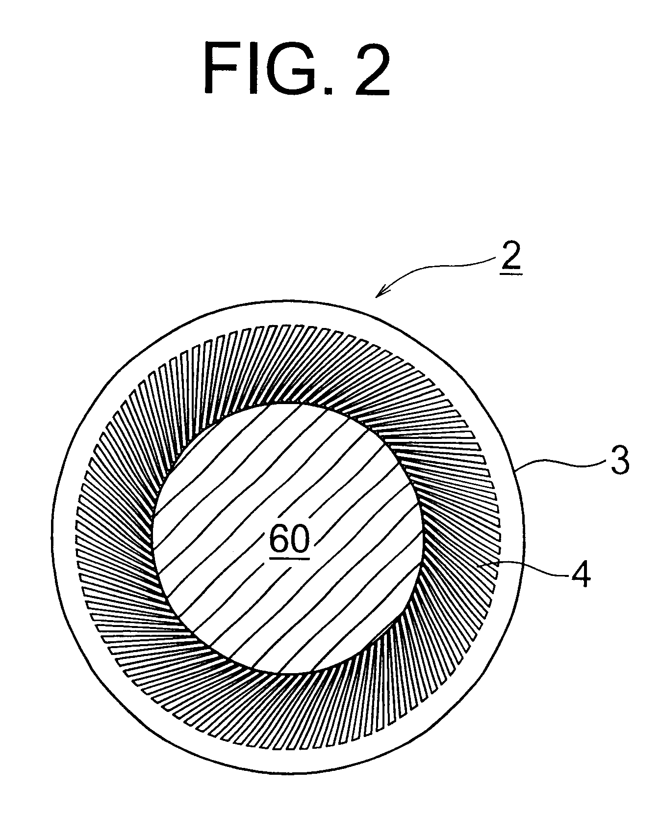
A brush seal unit 2P shown in FIG. 3 is a second embodiment according to the present invention. A plurality of the brush seal units 2P are laminated to form a brush seal 2 according to the amount of the pressure of the sealed fluid. The inner circumference side of the thin plates forming an annular shape is processed to form the slits 9 by etching, pressing, electric discharging or the like, such that the brush seal unit 2P has a brush section 2a in the strip like shape. Its outer circumference side is formed into a base part 2b of the thin plate without slits as a unit such that the brush section 2a will not be removed.

Each slit 9 is formed as a triangular space with narrow inner circumference side. The slit may be formed in a parallel space if necessary. The slit 9 forms a brush section 8 slanting toward the rotational direction of the rotor 60, and the tilt angle of the brush section 8 is determined, depending on the rotor (60) speed or the like. The brush section 8 may be formed...

third embodiment

FIG. 4A is a partial plan view of a brush seal device 1 shown in FIG. 1, viewed from the inner diameter side. FIG. 4B is an enlarged view of the portion C, shown in FIG. 4A. Each of FIGS. 4A and 4B shows a brush seal device 1 according to the present invention.

In FIG. 4A, a brush seal 2 is comprised of brush seal units 2P laminated in eight layers. As shown in enlarged view of FIG. 4B, a cross section of a brush part 8 is formed in a square shape which are arranged such that slits 9 will not be in a row in the direction of pressure action of the sealed fluid. By arranging like this, leakage of the sealed fluid is prevented, thereby to improve the sealing ability.

In FIG. 4B, each layer of brush seal 2 is comprised of two brush seal units 2P having the same inner diameter and alternately located to form a recess and projection portion 13 in the free end 5 as shown in FIG. 5.

fourth embodiment

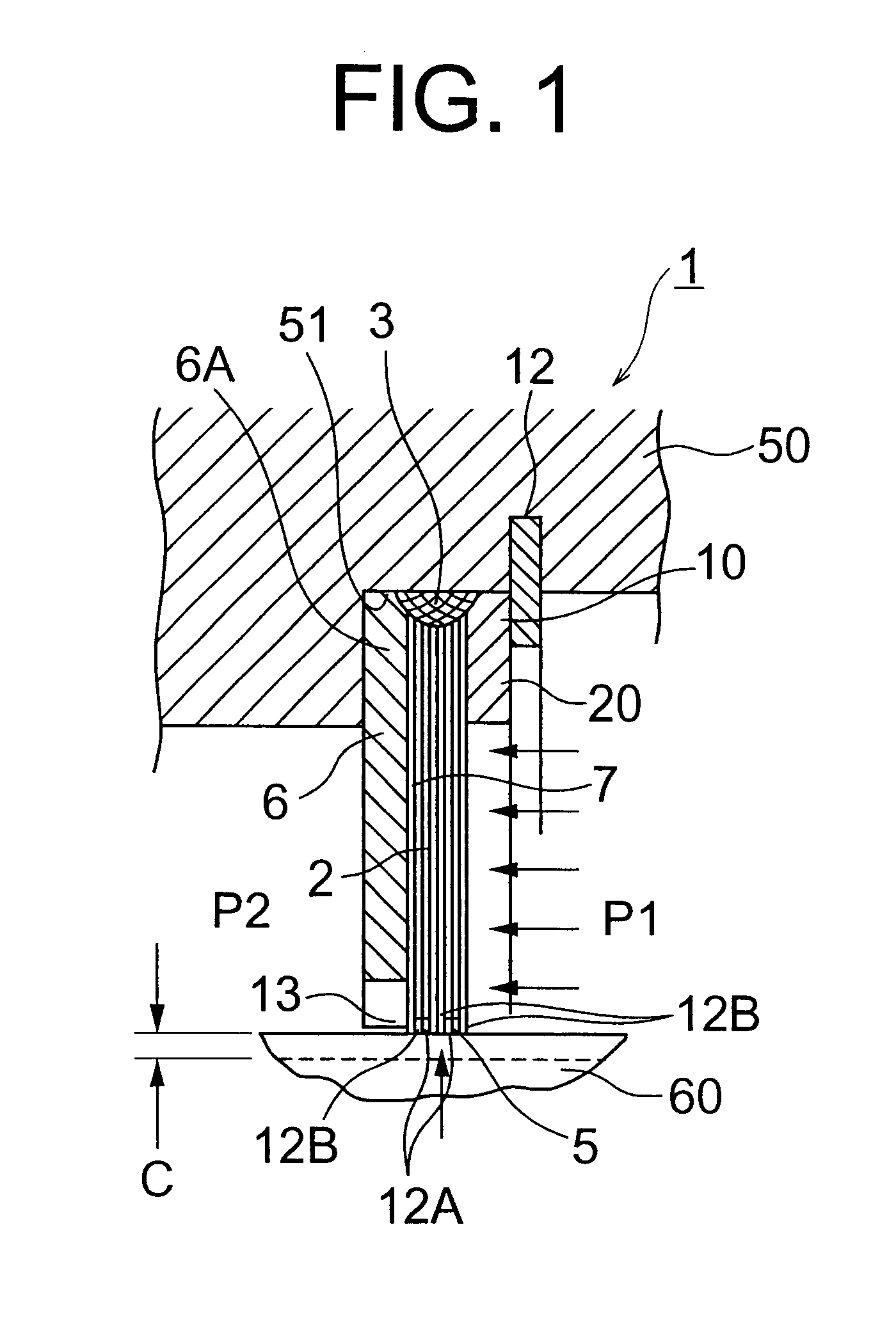
FIG. 5 is a partial sectional view of a brush seal device 1. Also, FIG. 5 shows the brush seal device 1 according to the present invention.

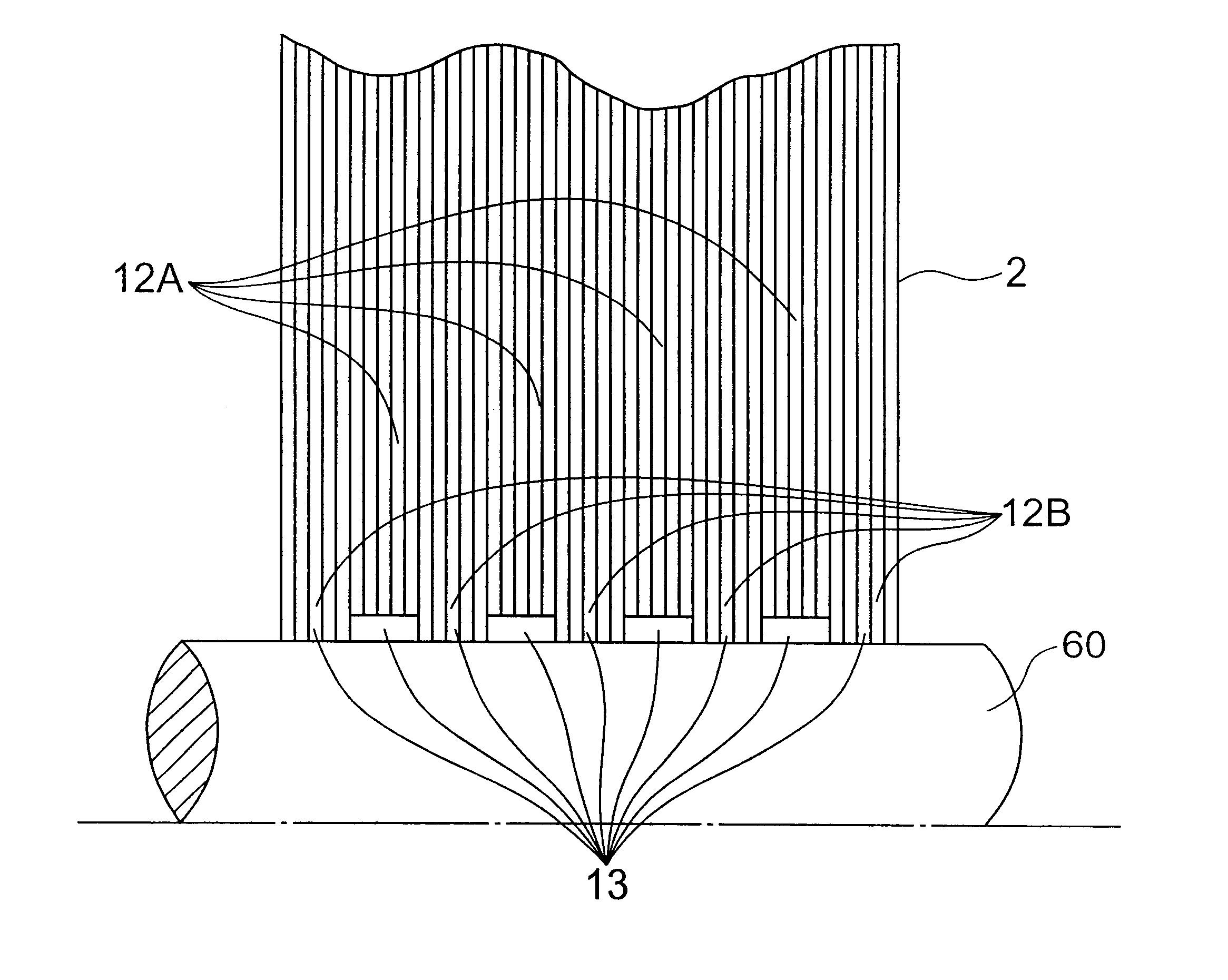
In FIG. 5, a brush seal 2 is comprised of five brush seal units 2P laminated to form a recess layer 12A and the same number of brush seal units 2P laminated to form a projection layer 12B, which are alternately laminated to form nine layers in total. Also, a recess and projection portion 13 is formed in the free end 5.

For the recess and projection portion 13, a various kinds of recess and projection portion 13 are formed, depending on the number of lamination layers of the recess layer 12A, the number of lamination layers of the projection layer 12B, and the number of layers of each layers of the recess layers 12A and the projection layers 12B. The width of the recess and projection portion 13 is determined, depending on the pressure of the sealed fluid or the like.

A cross section of the brush part 8 is usually formed in a square shape. When a re...


PUM


Abstract

When a clearance between a rotor and the free end of a brush seal of thin plates becomes larger by oscillation of the rotor or the like, the enlarged clearance is effectively sealed. In order to achieve this effect, in a brush seal device, brush seal units as recess layers and brush seal units as projection layers are stacked in the direction of the pressure of the sealed fluid to form recess and projection portion on its free end. The inner diameter of the recess layer is different from that of the projection layer.

Description

1. Field of the InventionThe present invention relates to a brush seal device. More particularly, the present invention relates to a brush seal device having a brush seal mounted on one of two components displaceable relatively between the two components, wherein the brush seal is capable of resiliently deforming to follow the change of the clearance between the two components even if the relative change between the two components occurs.2. Description of the Related ArtAs one related to the present invention there exists a brush seal device 100, as shown in FIG. 8. FIG. 8 is a sectional view of a brush seal device 100 mounted between a rotary shaft 120 and a casing 110 through which the rotary shaft 120 passes. The casing 110 is a component disposed on the stationary side of a steam turbine or gas turbine. The brush seal device 100 is mounted to the casing 110 to seal fluid by separating the space between the casing 110 and the rotary shaft 120.The brush seal device 100 is formed i...

Claims


Application Information

Patent Timeline
Patent Type & Authority Patents(United States)
IPC IPC(8): F16J15/32F16J15/22F16J15/3288
CPCF16J15/3288F16J15/3292
Inventor INOUE, HIDEYUKI
Owner EAGLE INDS
Why Eureka
Try Eureka