

Method of directly making rapid prototype tooling having free-form shape
a technology of free-form tooling and tooling, which is applied in the direction of liquid surface applicators, coatings, metallic material coating processes, etc., can solve the problems of poor microstructure, high residual stress, and undesirable phases
- Summary
- Abstract
- Description
- Claims
- Application Information
AI Technical Summary
Problems solved by technology
Method used
Image

Examples
Embodiment Construction
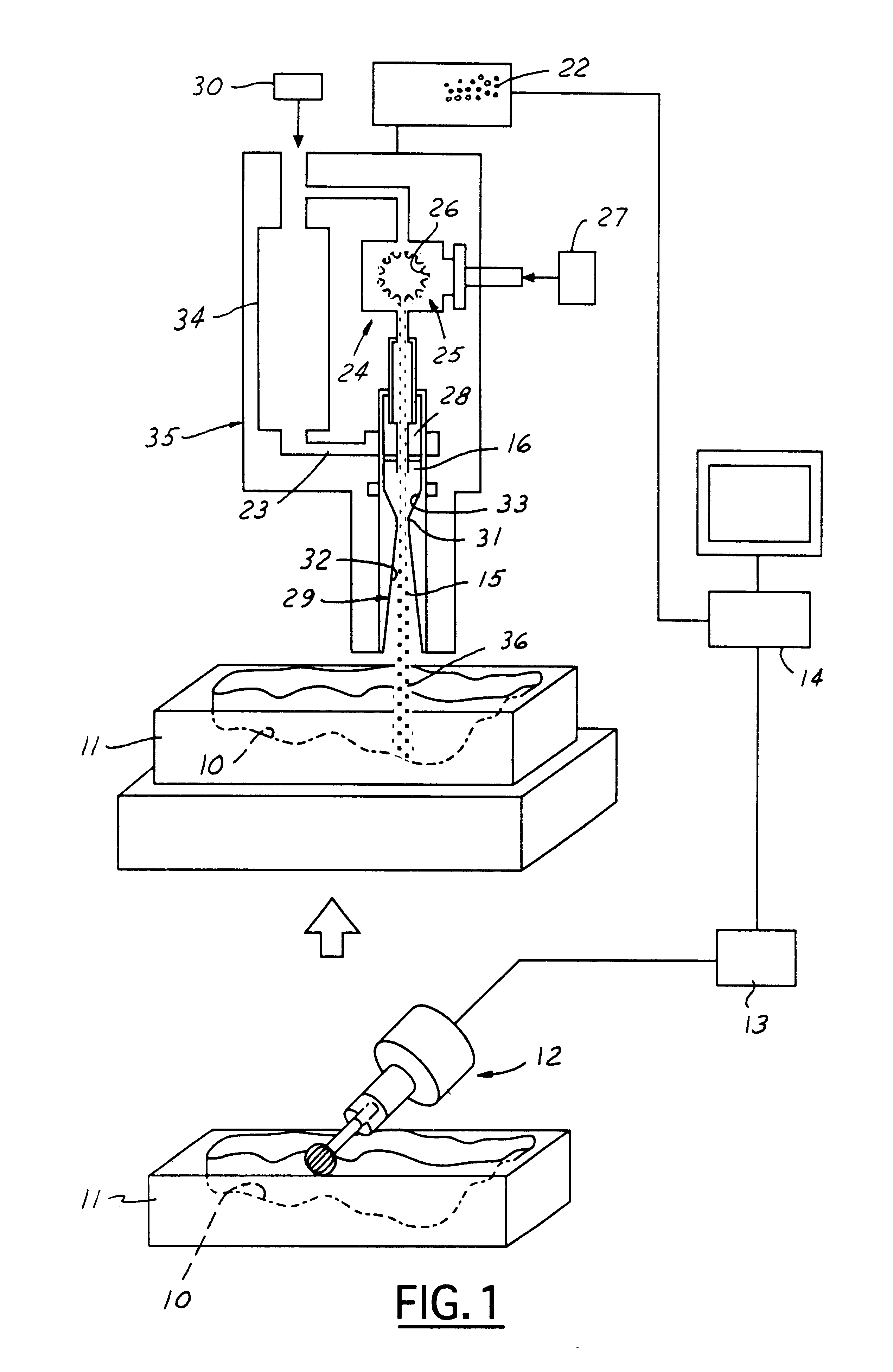
As shown in FIG. 1, the first step of the process is to machine a free-form contoured surface 10 into a "tooling" base constituted of a soft machineable metal, such as aluminum. Machining 12, such as by milling, grinding or boring, controlled by an NC module 13, is carried out to conform with a computer software model of the part in computer 14; such machining brings the contoured surface 10 of the base to near-net shape relative to the model, allowing parts to be made from such tooling. "Tooling" is used herein to mean dies or patterns that are used repeatedly to replicate a part or other configuration by forging or casting metal against the tooling. Aluminum is preferably selected for the tooling base because: (i) it is easily machined with speed and with little effort, and (ii) it absorbs mechanical and thermal shock better than steel. Other equivalent soft metals that can be used in place of aluminum may be selected from the group comprising: copper, zinc and aluminum alloys.
Als...
PUM
| Property | Measurement | Unit |
|---|---|---|
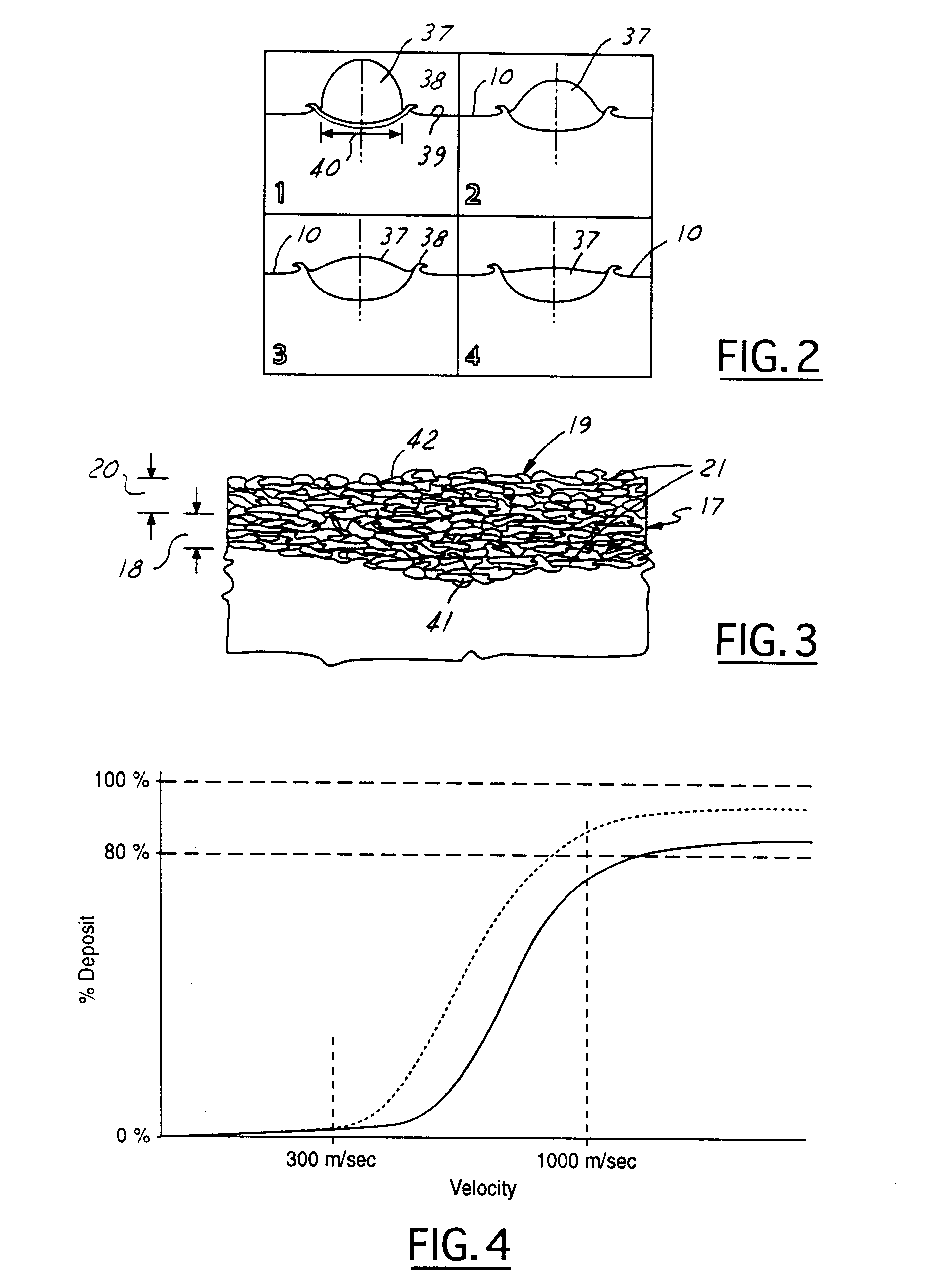
| critical velocity | aaaaa | aaaaa |
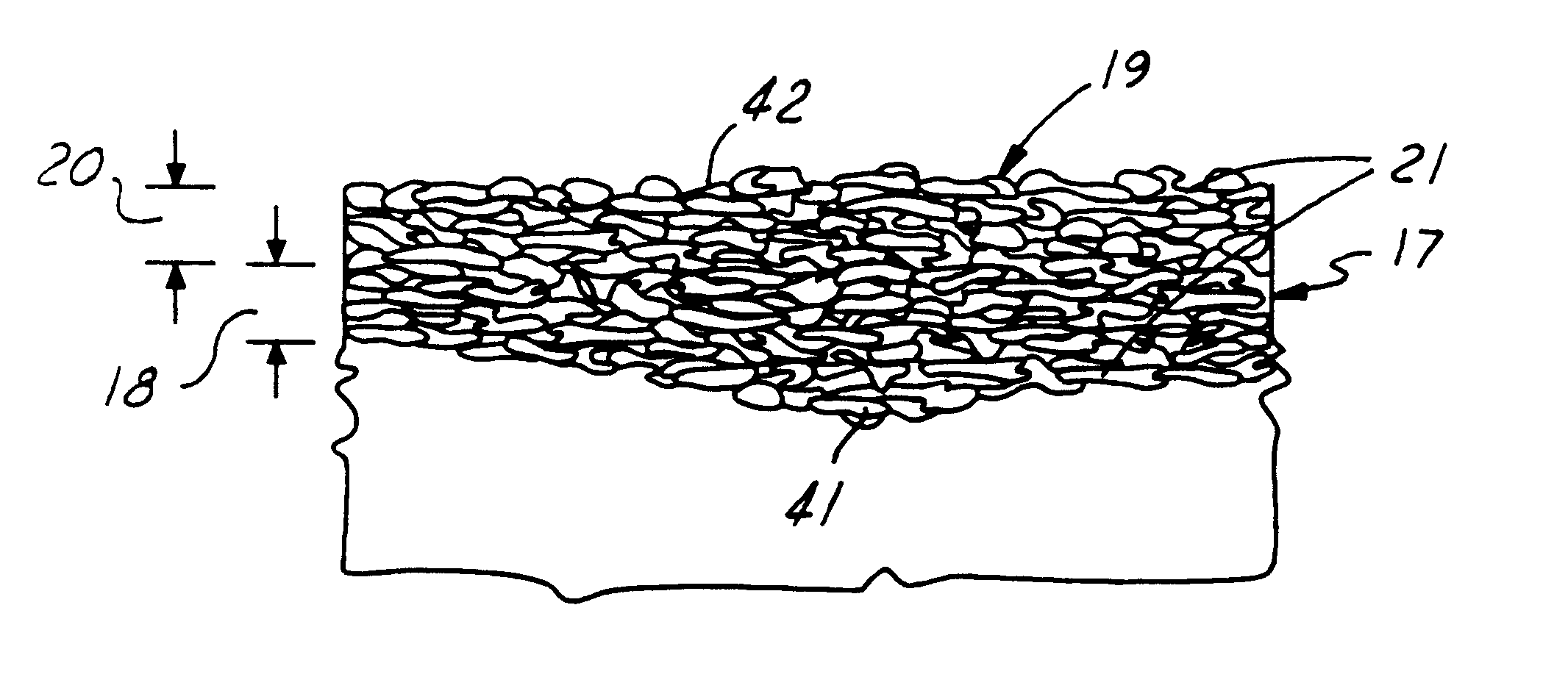
| thickness | aaaaa | aaaaa |
| thickness | aaaaa | aaaaa |
Abstract
Description
Claims
Application Information