Micro-ring cavity gyroscope with magnetic field lock-in minimization

a micro-ring cavity, laser gyroscope technology, applied in the direction of speed measurement using gyroscopic effects, instruments, surveying and navigation, etc., can solve the problem of reducing the ability of gyroscopes to measure rotation, reducing the ability of gyroscopes to accurately address the issue, and reducing the lock-in phenomenon.

Inactive Publication Date: 2003-08-05
DELAWARE UNIV OF A DE
View PDF7 Cites 14 Cited by
  • Summary
  • Abstract
  • Description
  • Claims
  • Application Information

AI Technical Summary

Benefits of technology

The present invention is broadly drawn to a micro-ring cavity gyroscope with a sensitivity axis, for sensing rotational motion, comprising: at least one micro-ring cavity laser comprising a light amplifying medium and magneto-optical material capable of generating an electromagnetic standing wave; at least one standing wave detection means; and means for generating a magnetic field that at least partially immerses said micro-ring cavity laser in magnetic field, wherein said standing wave detection means senses the position of the electromagnetic standing wave with respect to said micro-ring cavity laser, and the magnetic field perturbs the electromagnetic standing wave to minimize lock-in phenomenon enabling detection of rotational motion.
The transverse Faraday effect is proportional to the magnetic field and also proportional to the Verdet constant of the material. Additionally, the effect of axial magnetic field increases as the size of the cavity grows smaller. For example, for a GaAs cylinder of about 10 .mu.m in diameter, the same magnetic field of 10 mT results in the beat frequency of about 1.7 MHz. Conversely, if we use a larger cavity, the effect diminishes.
FIG. 4 shows another preferred modification of the disclosed invention, where the resonating cavity is in the form of a disc 8 on a pedestal 7. Such a microcavity semiconductor laser in the form of a disc on a pedestal is described by Ho, et al. in U.S. Pat. No. 5,825,799. A similar preferred embodiment incorporates a micro-ring cavity laser mounted on a pedestal. The embodiment depicted in FIG. 4 operates similarly to that described in FIGS. 1-3, except that the resonating cavity takes the shape of a disc. An advantage of the disc on pedestal is that light leakage to the substrate is minimized. Waveguide pickups can be used to sense the standing wave and lock-in phenomenon is eliminated in a similar way by applying a magnetic field.

Problems solved by technology

While these are proven devices, there are limitations to the reduction in size and cost achievable with these devices.
Lock-in is a common error source in ring laser gyroscopes which has been an issue for many years.
This tendency to lock-in reduces the gyroscopes's ability to measure rotation at low rates.
To date there is no micro-ring cavity laser gyroscope that adequately addresses the issue of lock-in and allows a micro-ring cavity laser based gyroscope to perform at low rates of rotation.

Method used


Image

  • Micro-ring cavity gyroscope with magnetic field lock-in minimization
  • Micro-ring cavity gyroscope with magnetic field lock-in minimization
  • Micro-ring cavity gyroscope with magnetic field lock-in minimization

Examples


Embodiment Construction

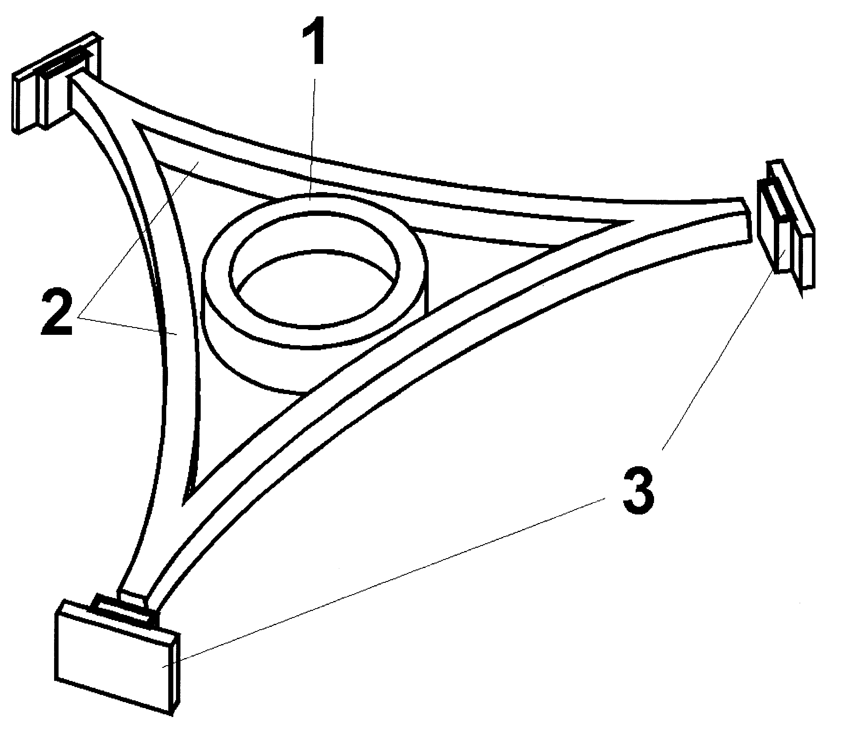
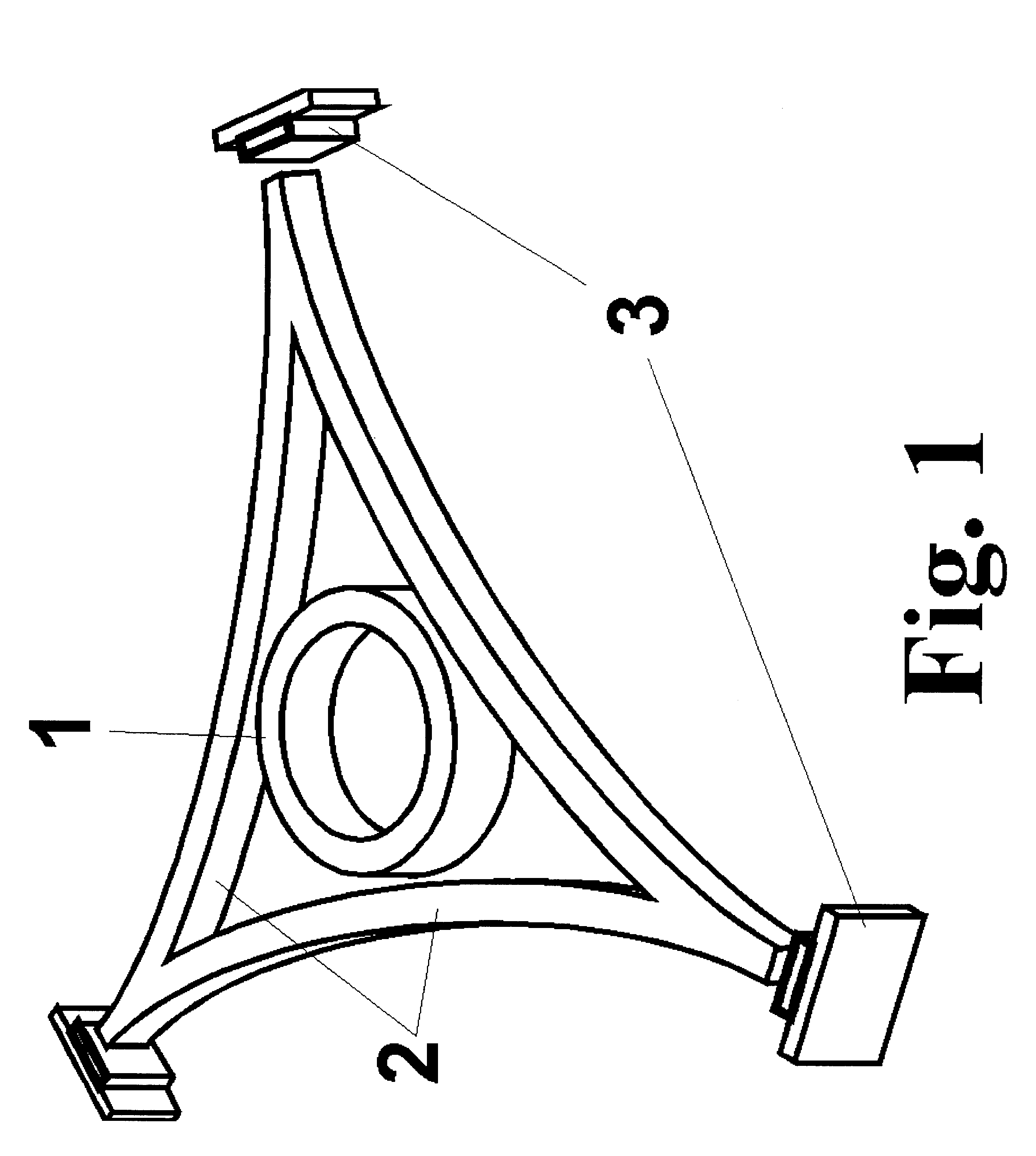
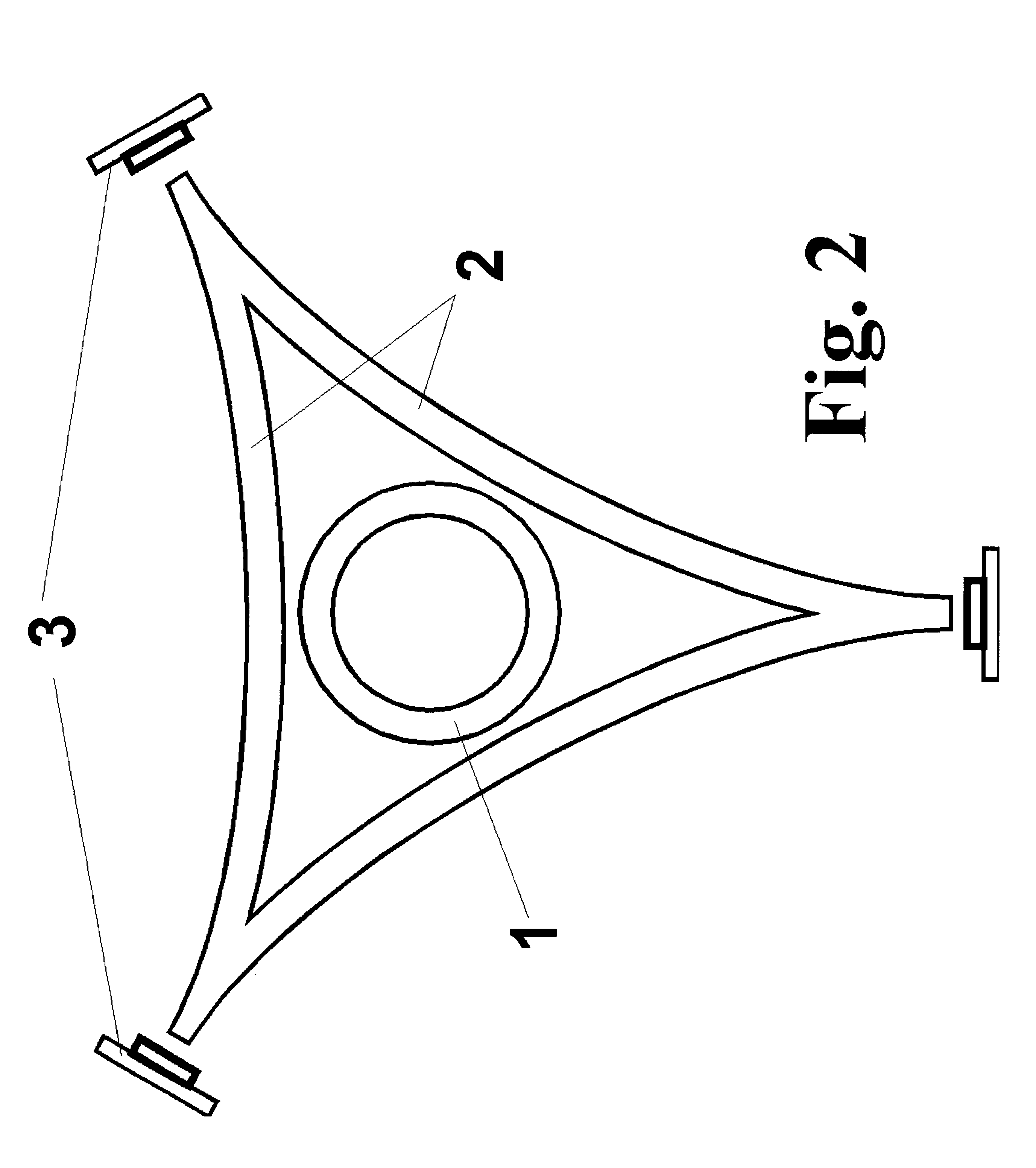
To make the micro-ring cavity laser gyroscope the necessary micro-ring cavity laser, waveguides, and the detectors are fabricated on a substrate. A number of methods have been developed for the fabrication of micro-ring lasers. Descriptions of the fabrication processes are available, for example, in A. F. Jezierski and P. J. R. Laybourn, Integrated semiconductor ring lasers, IEEE Proceedings, 135, (1988), pp.17-24; T. Krauss, P. J. R. Laybourn, J. Roberts, CW operation of semiconductor ring lasers, Electronics Letters, 26, (1990), pp.2095-2097; S. Oku, M. Okayasu, M. Ikeda, LowThreshold CW Operation of Square-Shaped Semiconductor Ring Lasers (Orbiter Lasers), IEEE Photonics Technology Letters, 3, (1991), pp. 588-590; and references therein.

Following the description of Jezierski, et al., a double heterostructure GaAs / GaAlAs is grown by MOCVD. Then the substrate is thoroughly cleaned and bonding pads are deposited. Deposition of the p-type contacts to the lasing structure follows. The...


PUM


Abstract

The invention is a compact optical gyroscope based on the Sagnac effect that combines a micro-ring cavity laser comprising a magneto-optical material and a magnetic field to circumvent the lock-in phenomenon at low rates of rotation. The invention also embodies novel processes for breaking lock-in using a transverse Faraday effect.

Description

BACKGROUND OF INVENTIONRing laser gyrocopes based on the Sagnac effect are commonly used in many modem navigational and aerospace guidance systems. In summary, two light beams are caused to propagate in opposite directions around a closed-loop path. Rotation of this closed loop path causes the effective path length in one direction to become shorter while lengthening the effective path length in the other direction. This change in path length is a direct measure of inertial rotation. Further details regarding the general operation of a ring laser gyroscope may be found in U.S. Pat. No. 3,373,650, by J. E. Killpatrick.The two most widely used versions for both civilian and military applications are the Ring Laser Gyroscope (RLG), and the Interferometric Fiber Optic Gyroscope (IFOG). While these are proven devices, there are limitations to the reduction in size and cost achievable with these devices. Both systems are based on the construction of relatively long closed paths that are d...

Claims


Application Information

Patent Timeline
Patent Type & Authority Patents(United States)
IPC IPC(8): G01C19/68G01C19/64G01C19/66
CPCG01C19/66G01C19/68
Inventor MURAKOWSKI, JANUSZ A.PRATHER, DENNIS W.
Owner DELAWARE UNIV OF A DE
Why Eureka
Try Eureka