
Adjustable clean-air flow environment

a technology of clean air flow and environment, which is applied in the direction of isotope separation, dispersed particle filtration, combinatorial devices, etc., can solve the problems of difficult to maintain such a gas flow, difficult to stay within the guidelines at the work surface or within the work zone, and long distances of gas filtering and moving

Inactive Publication Date: 2003-10-14
STRATOTECH CORP
View PDF123 Cites 43 Cited by
  • Summary
  • Abstract
  • Description
  • Claims
  • Application Information

AI Technical Summary

Benefits of technology

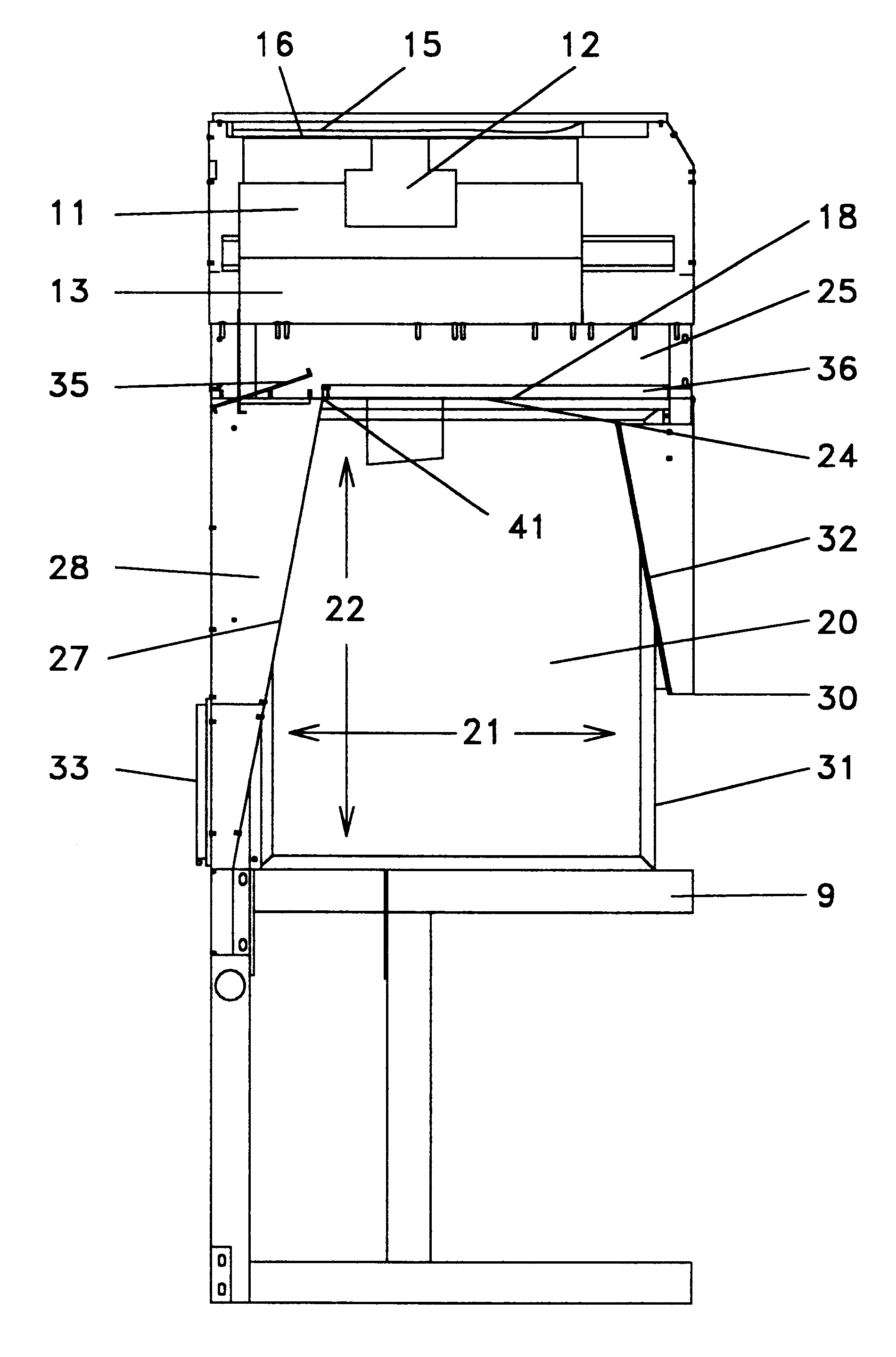
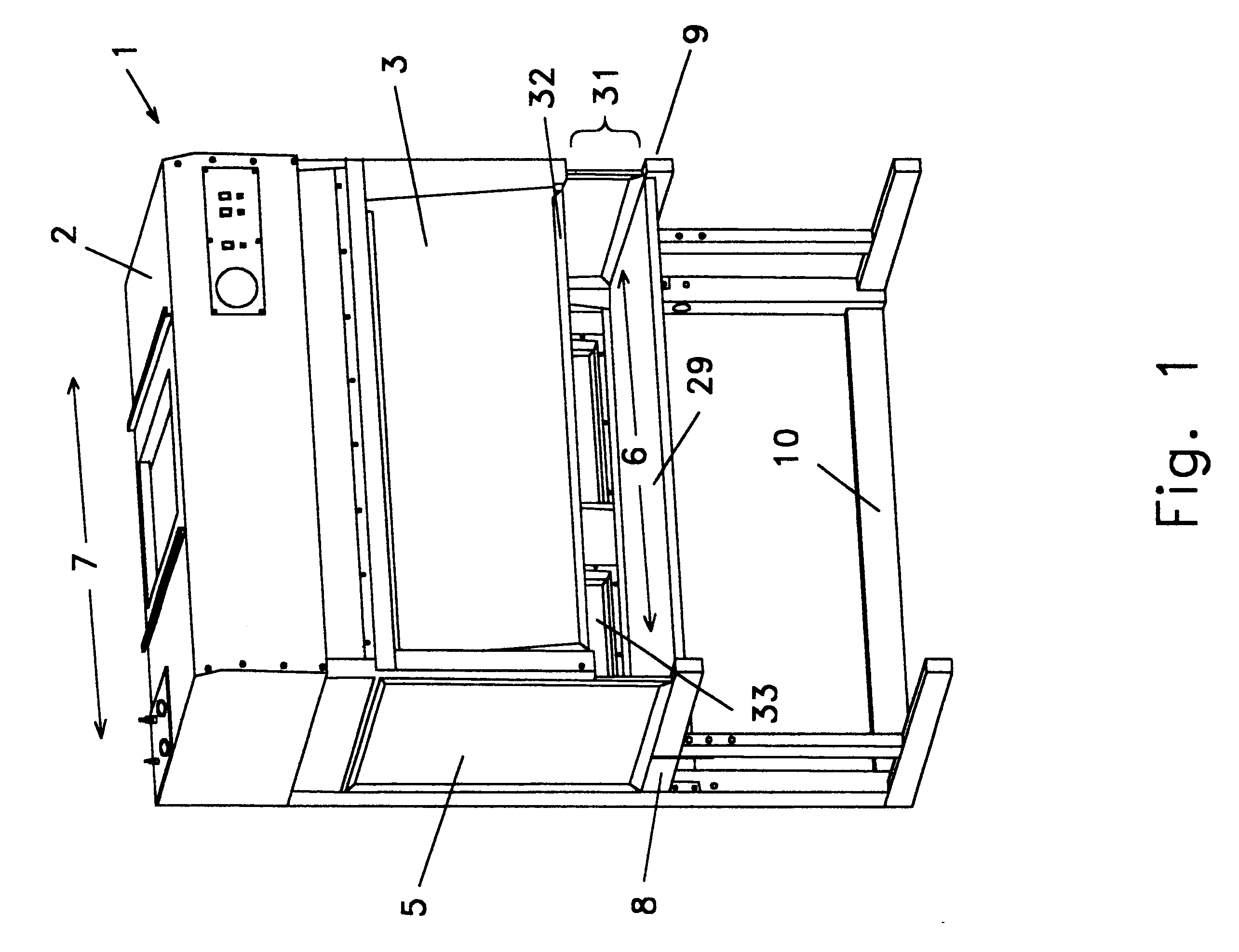
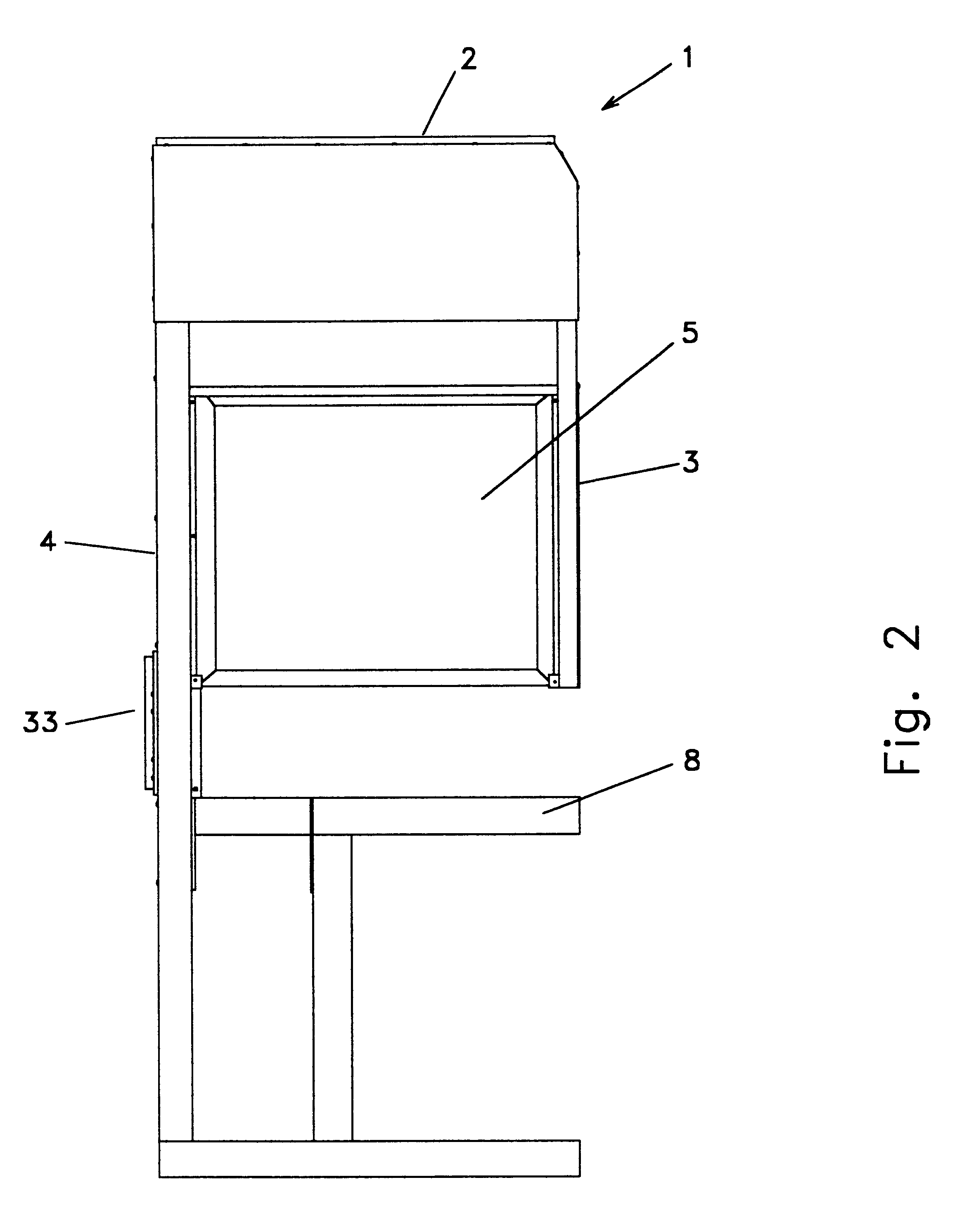
Enclosures having adjustable filtered gas flow environments and methods of enclosed pressure differential distribution technology provide material handling substantially free from airborne particulate contamination.
A second broad object of particular embodiments of the invention can be to allow an operator to be external from the filtered gas flow space. Only the operator's hands and a portion of the arms may be inside the filtered gas flow space and down stream from the material being isolated from airborne micro-particulates. This approach eliminates many of the costs and constraints of a clean room environment, including gowning areas, air showers, clean room suits, or the like. Operator comfort or ergonomics may also be addressed when the operator is external to the filtered gas flow space.
Another significant object of particular embodiments of the invention can be to configure plenums which convert filtered gas flow from the gas flow generator having a first direction of flow to a second direction of flow at the perforated surface of the plenum adjoined to the filtered gas flow space. This object of the invention may also include the above-mentioned objects of the invention such as distributing filtered gas to the entire surface area of the perforated surface of the plenum that adjoins the plenum space, and providing substantially uniform gas velocity at the perforated surface of the plenum that adjoins the filtered gas flow space.
Yet another object of particular embodiments of the invention can be to allow for easy room-side maintenance which reduces equipment down time. There may be easy access to the gas filters for more frequent or easier preventive maintenance. There may also be a utilities attachment panel on top of the unit that allows for easy hook-up of power and other attachments which go to the control panel or optional utility ports.

Problems solved by technology

A significant problem with large clean room environments may be that gas must be filtered and moved long distances, while passing by people, machines, and open space.
It is difficult to maintain such a gas flow and keep it within the Federal Standard 209 guidelines for particulate contamination.
It can be even more difficult to stay within these guidelines at the work surface or within the work zone.
Another significant problem with clean room environments may be that it is more costly to maintain clean room environments, than a smaller, more modular clean environments.
This requires additional space or cost for facilities and supplies.
In addition, this means that there must be aisle ways, standing or sitting areas, or the like that are part of the clean environment further adding to possible sources of contamination or adding additional cost to the clean room solution.
Even though small clean environments are desirable and generally used in manufacturing processes which require filtered gas environments, there are major problems which remain unresolved in the small clean environment industry.
A first problem can be the incompatibility of different clean environment enclosures which can be different shapes and sizes and may not be designed for being coupled or linked together.
These variations impose numerous problems with respect to material handling since even working surface heights may differ by inches, or the overall depth from one clean environment enclosure to the next may differ by several inches.
In addition, even where the overall dimensions are compatible there may not be compatible side access panels on certain units which may prohibit linking units together in a side-by-side arrangement.
Accommodating these variations may lead to wasted factory floor space which may not be reclaimed.
A second problem can be that existing clean enclosures do not distribute filtered gas to the entire surface of the gas flow delivery panel (or perforated plenum panel) adjoined to the clean work zone (or filtered gas flow space).
This may result in only a portion of the surface of the perforated plenum panel delivering filtered gas to the filtered gas flow space.
A third problem can be that existing clean environment enclosures do not adjoin the perforated surface of the plenum to the entire flow path defined by the filtered gas flow space.
A fourth problem can be that existing clean environment enclosures do not allow selectable gas flow within the filtered gas flow space of the clean environment enclosures.
A fifth problem can be that existing clean environment enclosures do not provide filtered gas flow having a substantially uniform velocity from the entire surface of the perforated plenum panel adjoined to the filtered gas flow space.
A sixth problem can be that existing clean environment enclosures do not position the area of minimum velocity in the filtered gas flow space at a location most distal from the access to the filtered gas flow space.
A seventh problem can be that existing clean environment enclosures may not be adjusted to allow gas flow having velocity gradient substantially symmetrical about a plane which bisects the clean work zone in a diagonal fashion.
As such, there may be irregular gas flow characteristics within the filtered gas flow space which may make it difficult to predict the gas flow velocity at any particular area within the filtered gas flow space.
As such, the filtered gas flow within the filtered gas flow space may be unsuitable for particular applications, or may be difficult to tailor for particular applications.
An eighth problem can be that existing clean environment enclosures do not address the need for flexibility to accommodate changes in manufacturing processes and to accommodate shifts in market demand as products proceed through their life cycle.
These expansions and contractions typically require additional purchases of equipment (i.e. vertical or horizontal clean environment enclosures) or clean room reconstruction activities and may also require unneeded equipment to stand idle or be stored pending possible future use.

Method used


Image

  • Adjustable clean-air flow environment
  • Adjustable clean-air flow environment
  • Adjustable clean-air flow environment

Examples


Embodiment Construction

The invention constitutes a pressure differential distribution enclosure and methods which disclose how to make and how to use pressure differential distribution enclosure technology. Specifically, pressure differential distribution enclosure technology relating to filtered gas flow material handling environments.

The basic concepts of pressure differential distribution enclosure technology, or as it may relate to filtered gas flow material handling environments are to be understood as applicable to a variety of circumstances where the distribution of gas pressure or the distribution of gas velocity within an enclosure may be desired, for example, clean room technology, fume hood technology, material handling, or material containment technology, or the like, as would be readily understood by those skilled in the arts.

Moreover, while this disclosure provides specific descriptions of embodiments of apparatus and methods relating to pressure differential distribution enclosures, or filt...


PUM

PropertyMeasurementUnit
Fractionaaaaaaaaaa
Fractionaaaaaaaaaa
Angleaaaaaaaaaa

Abstract

Enclosures having adjustable clean gas flow environments and methods of enclosed pressure differential distribution technology. Specifically, clean gas flow enclosures, which provide for the isolation of materials from airborne micro-particulate contamination. An embodiment of the invention utilizes a small footprint, modular, selectable, clean-gas flow environment for handling and isolating materials. The environment can be a clean room class environment by providing filtered gas from a gas flow generator (12) through a gas filter (13) to a filtered gas flow space (20). An embodiment of the invention provides a first plenum (23) and a second plenum (26) so that both a horizontal filtered gas flow and vertical filtered gas flow may be used separately or in combination within the same filtered gas flow space (20).

Description

TECHNICAL FIELDGenerally, the invention relates to enclosures having adjustable clean gas flow environments and methods of enclosed pressure differential distribution technology. Specifically, clean gas flow enclosures, which provide for isolation of materials from airborne micro-particulate contamination.BACKGROUNDClean (or filtered) gas flow material handling systems are used in manufacturing to isolate clean materials from contamination by airborne macro-particulates or micro-particulates. There are three major categories of smaller filtered gas flow material handling systems, which are categorized based on the type of air flow: 1) Vertical Laminar Flow, 2) Horizontal Laminar Flow, and 3) Exhaust or Fume hoods. Each of the three types of devices have advantages depending on the various types of material handling application requirements. A focus of some of the embodiments of this invention are on the vertical laminar flow and the horizontal laminar flow categories. Particular emb...

Claims


Application Information

Patent Timeline
IPC IPC(8): B01D46/02F24F3/16F24F7/06B01D46/00B08B15/02
CPCB01D46/0013B08B15/023F24F3/1607B01D2267/40Y10S55/29F24F2011/0004Y10S55/18Y10S55/46F24F3/163B01D46/00
Inventor SIEMERS, WARREN G.HAMOR, GARY D.
Owner STRATOTECH CORP
Learn More