
Tunable semiconductor laser having cavity with wavelength selective mirror and Mach-Zehnder interferometer

a laser and wavelength selective mirror technology, applied in the direction of laser details, laser optical resonator construction, optical resonator shape and construction, etc., can solve the problems of difficult reconciliation of requirements, complex tuning pattern of tuning such devices, and optical signals not at resonance wavelengths of fabry-perot side channels not effectively coupled with reflective etalon

Inactive Publication Date: 2003-10-14
SPECTRASENSORS INC
View PDF34 Cites 21 Cited by
  • Summary
  • Abstract
  • Description
  • Claims
  • Application Information

AI Technical Summary

Problems solved by technology

Such requirements often are not easily reconciled with the wide tunability, particularly with relatively inexpensive WTLs.
Furthermore, while monolithic semiconductor WTLs, currently the state of the art devices, provide the necessary degree of miniaturization and ruggedness, tuning of such devices involves a complicated tuning pattern.
Optical signals not at the resonance wavelengths of the Fabry-Perot side channel do not couple effectively into the reflective etalon.
As the optical signals propagate through the wide tuning port, the signals are split between two channels of differing lengths resulting in optical interference.
The optical interference limits the ability of the laser cavity to resonate at wavelengths wherein destructive interference occurs.
As a result, resonance within the overall laser cavity is substantially limited to within a broad peak determined by the relative lengths of the two channels.
The amplitudes of sidebands are thereby greatly limited.

Method used


Image

  • Tunable semiconductor laser having cavity with wavelength selective mirror and Mach-Zehnder interferometer
  • Tunable semiconductor laser having cavity with wavelength selective mirror and Mach-Zehnder interferometer
  • Tunable semiconductor laser having cavity with wavelength selective mirror and Mach-Zehnder interferometer

Examples


Embodiment Construction

With reference to the remaining figures, exemplary embodiments of the invention will now be described.

DWDM with Mach-Zehnder / Ring-Resonator WTLs

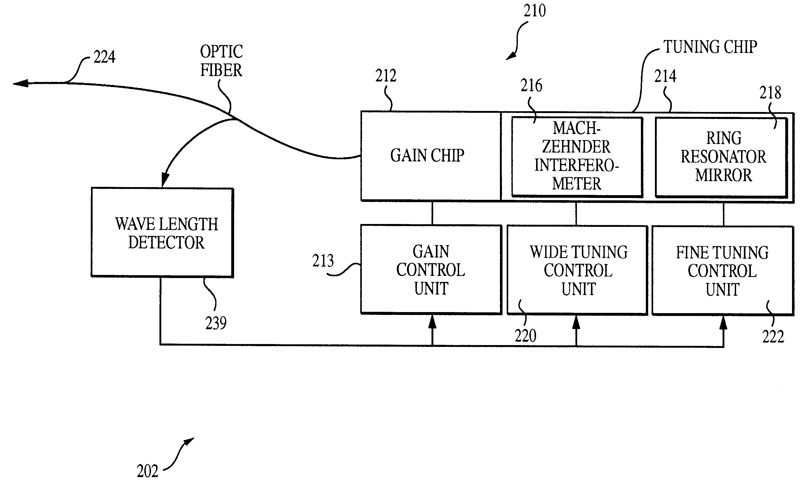
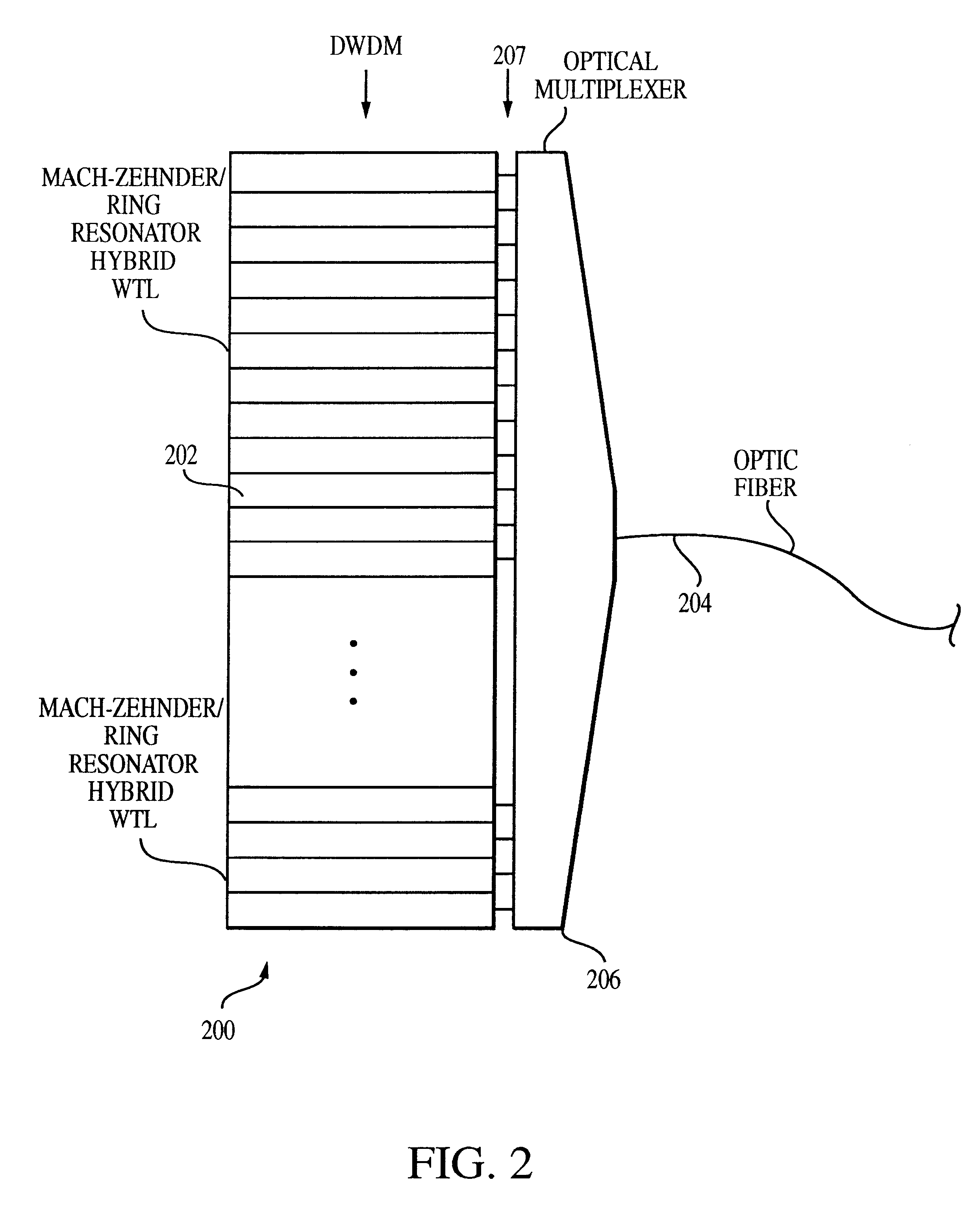
FIGS. 2-8 illustrate an exemplary embodiment of a DWDM having a hybrid WTL formed using a Mach-Zehnder interferometer as a wide tuning port and a ring resonator as a wavelength-selective mirror. Referring first to FIG. 2, a DWDM 200 is illustrated with forty individual hybrid WTLs 202 for transmitting optical signals on forty ITU C-band channels via a single optic fiber 204. An optical multiplexer 206 couples signals received from the individual hybrid WTLs via a set of intermediate optic fibers 207 into output optic fiber 204 to a demultiplexer (not shown) provided at the far end of the optical fiber. Each hybrid WTL is tuned to transmit optical signals at a wavelength selected from the forty channel ITU C band for use in optically transmitting signals along output optic fiber 204. The signals may be, for example television signals, telepho...


PUM


Abstract

The semiconductor laser has a resonance cavity composed of a gain chip, a Mach-Zehnder wide tuning port, and a wavelength-selective mirror component formed either as a ring resonator or a reflective Fabry-Perot etalon. Optical signals generated by the gain chip propagate through the wide tuning port and into the wavelength-selective mirror component and are then reflected back to the gain chip. The wavelength-selective mirror component is configured to reflect only those optical signals having wavelengths within a set of sharp peaks so that the laser cavity resonates only within the sharp peaks. The wavelength-selective mirror component is heated to adjust internal dimensions to maintain one of the sharp peaks at a selected emission wavelength. As optical signals pass through the wide tuning port, the signals are split between two channels of differing lengths resulting in optical interference. The optical interference limits the ability of the laser cavity to resonate at wavelengths other than near the center of a single broad peak determined by the relative lengths of the two channels. The wide tuning port is heated to vary the relative lengths of the two channels to maintain the single broad peak at the selected transmission wavelength. In this manner, the laser cavity is controlled to resonate substantially only at the single selected wavelength. Resonance at any of the other wavelengths reflected by the wavelength-selective mirror component is greatly limited, thereby significantly reducing transmission sidebands generated by the laser. Specific implementations of the ring resonator mirror and the reflective etalon are described.< / PTEXT>

Description

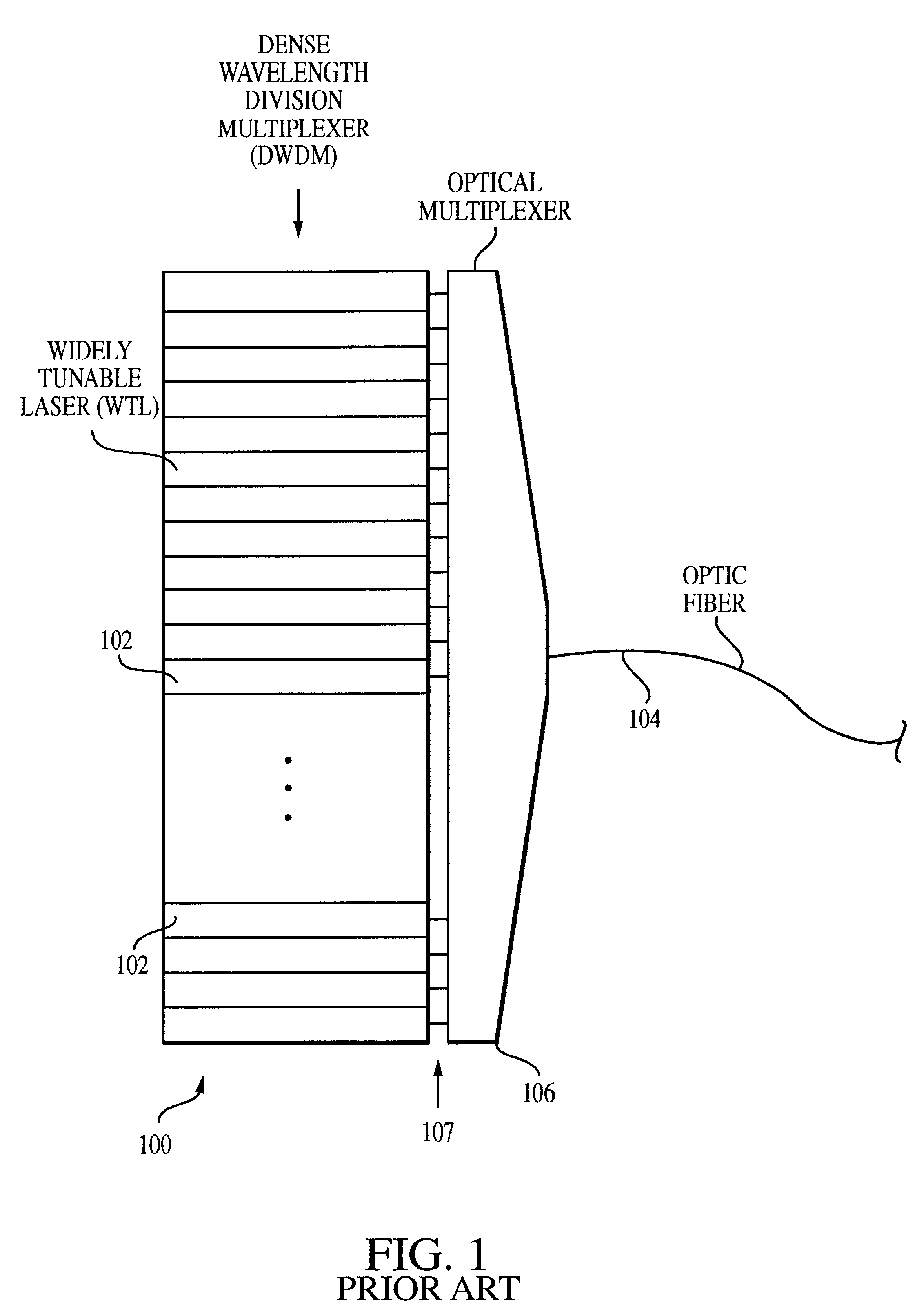
1. Field of the InventionThe invention generally relates to tunable lasers and in particular to tunable lasers for use in a dense wavelength division multiplexers (DWDM).2. Description of the Related ArtA DWDM is a device for simultaneously transmitting a set of discrete information channels over a single fiber optic transmission line. A conventional fiber optic transmission line is capable of reliably transmitting signals within a bandwidth of 1280 to 1625 nanometers (nm), the "low loss" region for silica fiber. Within that overall bandwidth, the International Telecommunications Union (ITU) has defined various transmission bands and specified certain transmission channel protocols for use within each transmission band. One example of a transmission band is the ITU "C" band, which extends 40 nm from 1565 nm to 1565 nm. Within the C band, specific transmission channel protocols of 40, 80, or 160 discrete channels are defined and, for each protocol, the ITU has defined a grid of trans...

Claims


Application Information

Patent Timeline
Patent Type & Authority Patents(United States)
IPC IPC(8): H01S5/00H01S5/14H01S5/0687H01S5/10
CPCH01S5/141H01S5/0687H01S5/1032H01S5/1028
Inventor KSENDZOV, ALEXANDERMAY, RANDY DEAN
Owner SPECTRASENSORS INC
Learn More