Image-forming apparatus for use with negatively-charged toner and featuring a negatively-chargeable image-bearing member, and process cartridge using same

a technology of negative-charged toner and image-bearing parts, which is applied in the direction of electrographic processes, instruments, corona discharge, etc., can solve the problems of faulty image called toner spots around line images, increase in toner consumption, and dark and dull images

Inactive Publication Date: 2003-11-11
CANON KK
View PDF13 Cites 7 Cited by
  • Summary
  • Abstract
  • Description
  • Claims
  • Application Information

AI Technical Summary

Problems solved by technology

Hence, in the formation of images like photographic images, too dense images may be formed as a whole, and the images may look dark and dull.
When the toner has a low quantity of triboelectricity, the toner may move in excess to line-image latent images to cause an increase in height of toner images on the photosensitive drum, resulting in an increase in toner consumption and causing a faulty image called toner spots around line images.
As the result, even though the toner has a proper quantity of triboelectricity at the initial stage, it becomes a toner having a low quantity of triboelectricity to cause problems such as crushed line images, spots around line images and an increase in toner consumption.
Moreover, the toner charged in a reverse polarity may adhere to nonimage areas on the photosensitive drum to appear as reversal fog, also causing such a problem that the...

Method used


Image

  • Image-forming apparatus for use with negatively-charged toner and featuring a negatively-chargeable image-bearing member, and process cartridge using same
  • Image-forming apparatus for use with negatively-charged toner and featuring a negatively-chargeable image-bearing member, and process cartridge using same
  • Image-forming apparatus for use with negatively-charged toner and featuring a negatively-chargeable image-bearing member, and process cartridge using same

Examples


example 2

In the contact developing system, since the photosensitive drum and the developing roller are rotated in contact with each other, the photosensitive drum surface may greatly be worn or scratched, compared with those in the non-contact developing system.

In the present Example, a photosensitive drum was used in which a protective layer was superposed on the charge transport layer so that the photosensitive drum was durable to wear and scratches occurring on the surface upon friction. As the toner, the toner (a) used in Example 1, having negatively chargeable properties, was used.

The protective layer serving as the surface layer of the photosensitive drum in the present Example was produced according to the following formulation.

100 parts by weight of antimony-containing fine tin oxide particles having an average particle diameter of 0.02 .mu.m, 100 parts by weight of a curable acrylic monomer, 0.1 part by weight of 2-methylthioxanthone as a photopolymerization initiator and 300 parts ...

example 3

is also described as a system in which the toner images are superimposed on the intermediate transfer belt 54 and then one time transferred to the transfer medium. The like effect is obtainable also when the toner images are directly sequentially superimposed on the transfer medium.

As multicolor, image-forming methods, a multicolor, image-forming method of what is called a tandem system is available in which a plurality of image-forming process units each internally provided with a photosensitive drum as the first image-bearing member. In this case, the construction described in Example 1 or in Example 2 is preferred.

example 4

In Example 4, the same image-forming apparatus as the image-forming apparatus used in Example 1 was used. As the photosensitive drum, a photosensitive drum A produced in the same manner as in Example 1 was used.

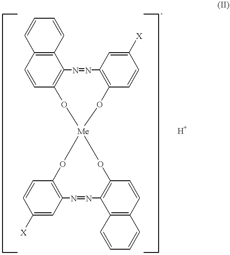
A negatively chargeable toner 10 used in Example 4 is described here. First, 100 parts by weight of polyester resin, 5 parts by weight of carbon black, 3 parts by weight of low-molecular-weight polyethylene and 2 parts by weight of a monoazo metal complex represented by the following Formula (II) were mixed using a Henschel mixer, and the mixture obtained was melt-kneaded by means of a twin-screw extruder. The resultant kneaded product was crushed by means of a hammer mill, and then the crushed product obtained was pulverized by means of a jet mill, further followed by air classification to obtain negatively chargeable toner particles with an average particle diameter of 7.5 .mu.m. This is designated as toner particles A.

To 100 parts by weight of the toner particles A thus ob...


PUM

PropertyMeasurementUnit
Electric potential / voltageaaaaaaaaaa
Surface potentialaaaaaaaaaa

Abstract

An image-forming apparatus includes an image-bearing member for holding thereon an electrostatic latent image; a charging device for electrostatically charging a surface of the image-bearing member; an exposure unit for forming the electrostatic latent image on the image-bearing member by exposing to light the image-bearing member having been charged by the charging device; and a developing unit which has at least a toner-carrying member for carrying and transporting a negatively-chargeable toner thereon and developing the electrostatic latent image by a contact developing system to form a toner image. In the triboelectric series relationship between the toner and a surface layer of the image-bearing member, the surface layer of the image-bearing member has a charge polarity which is a different polarity with respect to the charge polarity of the toner in the developing unit. The image-bearing member includes the electrostatic latent image including a surface potential, as a nonimage area potential (Vd) within a range of -500 to -800 V, and as an image area potential (Vl), at which the maximum toner image density is to be obtained, within a range of -50 to -200 V. A process cartridge includes the above-described image-bearing member.

Description

1. Field of the InventionThis invention relates to an image-forming apparatus employing an electrophotographic recording system having an exposure unit which radiates light modulated in accordance with image signals and a contact developing unit for developing electrostatic latent images formed by this exposure unit. More particularly, this invention relates to an image-forming apparatus which can prevent mismatching in the expression of density gradation and spots around line images from being caused by the shortage of charge quantity due to reversely charged toner. This invention also relates to a process cartridge used in the image-forming apparatus.2. Related Background ArtIn general, image-forming apparatus employing an electrophotographic recording system have a photosensitive member which is rotatively driven, a charging assembly which electrostatically charges the surface of the photosensitive member uniformly, an exposure means by which the surface of the photosensitive mem...

Claims


Application Information

Patent Timeline
IPC IPC(8): G03G13/06G03G13/08G03G9/09G03G9/08G03G9/097G03G9/087G03G15/00
CPCG03G9/08G03G9/08755G03G9/0904G03G13/08G03G9/092G03G9/097G03G9/09783G03G9/0918G03G15/00
Inventor KOBAYASHI, TETSUYAISHII, YASUYUKINAKAGAWA, TSUYOSHIUEHARA, SHINJI
Owner CANON KK
Why Eureka
Try Eureka