Vehicle axle suspension

a technology of axle suspension and axle spring, which is applied in the direction of shock absorbers, mechanical equipment, transportation and packaging, etc., can solve the problem of greater axle spring travel

Inactive Publication Date: 2003-11-25
SAF HOLLAND GMBH
View PDF36 Cites 23 Cited by
  • Summary
  • Abstract
  • Description
  • Claims
  • Application Information

AI Technical Summary

Benefits of technology

As a further development of this thought the covering may also consist of a flexible material, may rest with its bottom peripheral edge against the exterior of the pneumatic spring bellows and be taken along by them so that the accumulation of dirt as referred to above is avoided.
To prevent damage of the pneumatic spring bellows at the edges of the collar, the latter may be rounded.

Problems solved by technology

This results in greater axle spring travel.

Method used


Image

  • Vehicle axle suspension
  • Vehicle axle suspension
  • Vehicle axle suspension

Examples


first embodiment

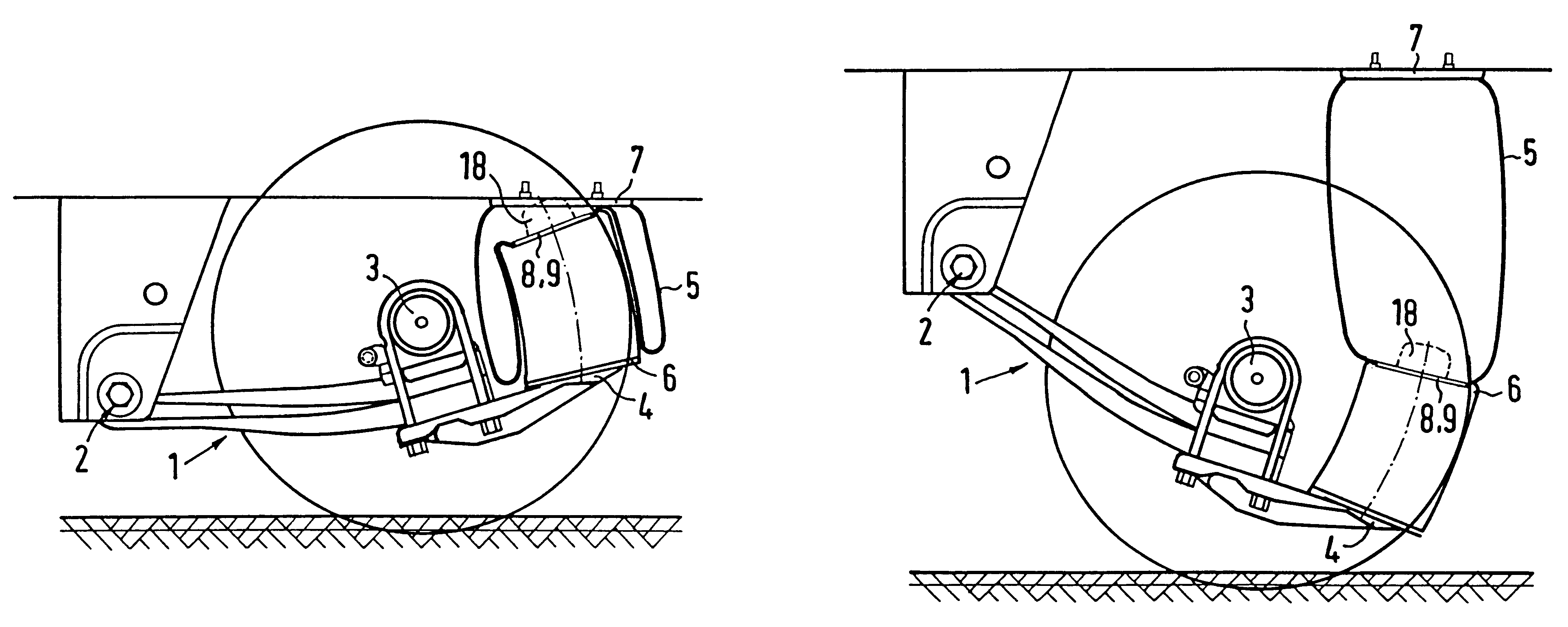
In FIGS. 4A to 4C the operation and the advantages of an axle assembly equipped with a plunger piston assembly 5, 6 as per the invention in comparison with the state of the art are easy to see. In the left half of the drawings, a plunger piston assembly 5, 6 according to the state of the art is shown, in the right half a plunger piston 6 shortened by the amount H (H=height of the collar 10). FIG. 4A shows the configuration in which the maximum possible bellows spring excursion is reached. As shown in FIG. 4A the plunger piston assembly 5, 6 according to the state of the art and as per invention are based on the same maximum bellows travel. This means, that as proposed by the invention, a plunger piston 6 shortened by the distance H can be used with pneumatic spring bellows 5 of the same length. FIG. 4B illustrates the configuration in which the leaf spring assembly 1 and therefore the axle aggregate of the vehicle is in an intermediate traveling position. Finally, FIG. 4C illustrate...

second embodiment

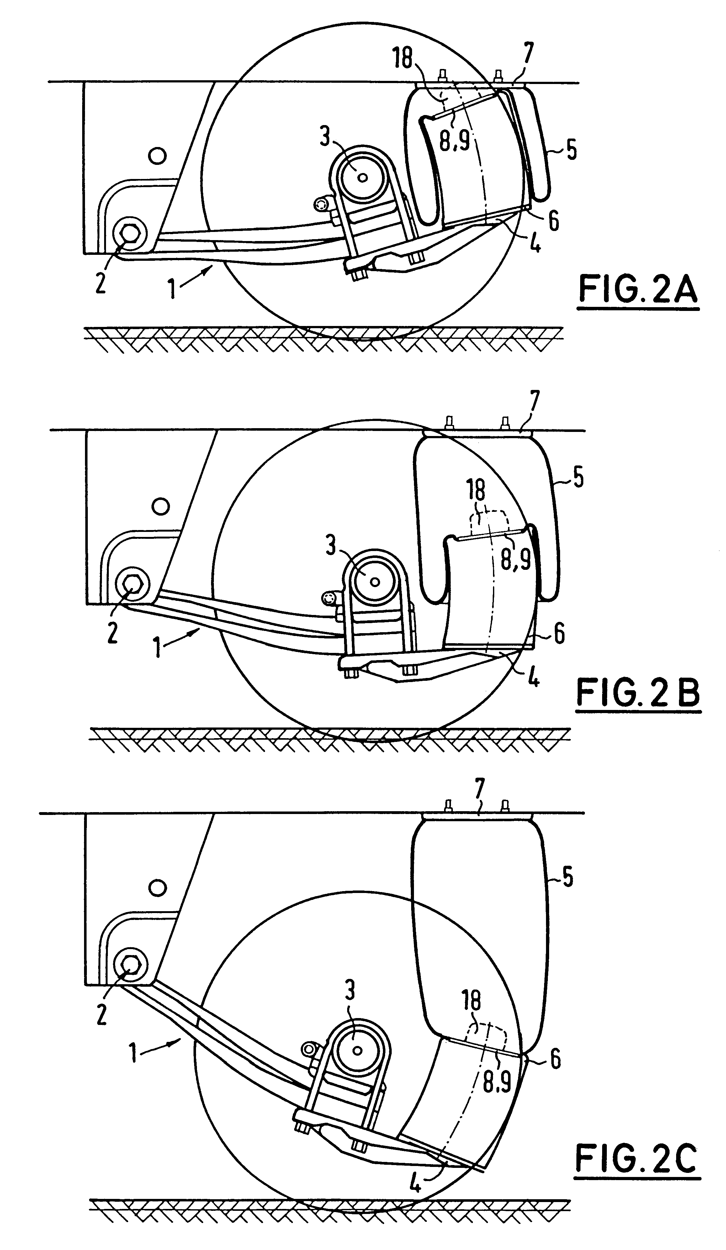
FIGS. 9A to 9B illustrate the operation of the plunger piston assembly for the invention whereby the pneumatic spring bellows 5 are installed directly at the peripheral edge 20 of the mounting plate 7 similar to FIGS. 4A to 4C. Here too the plunger piston 6 (and therefore the blocking length) is shortened by 1.times.H (=height of the independent collar 10). The same maximum stroke length as with the state of the art is obtained by lengthening the pneumatic spring bellows 5 by 1.times.H.

FIGS. 10A to 10C reflect the conditions shown in the FIGS. 5A to 5C for the second embodiment of the invention.

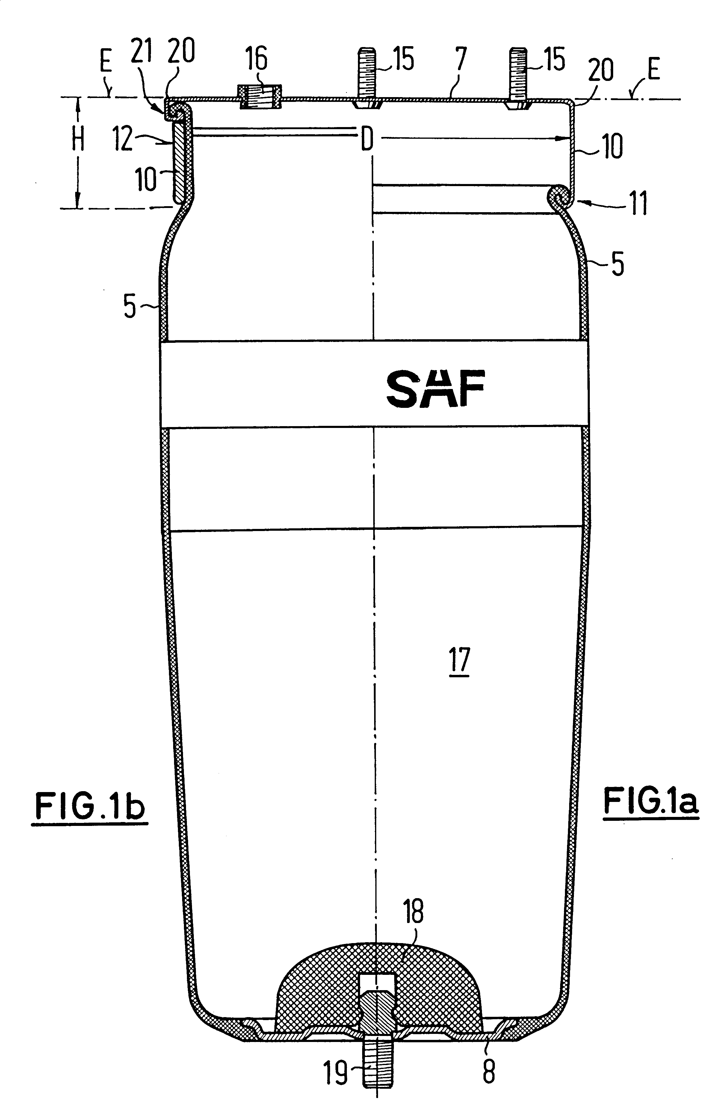
FIGS. 11A to 11C show how the pneumatic spring bellows 5 roll on and off the collar 10 which is in the form of an independent hoop encircling the pneumatic spring bellows 5 immediately adjacent to the bead 21 of the peripheral edge 20 of the mounting plate 7. The three embodiments differ in their contact area with the bead 21 and their rounding 22 of the collar 10 at its bottom end.

In a varia...


PUM


Abstract

An axle suspension for air-suspended utility vehicles and the like with which the vehicle chassis is supported by a pneumatic spring. The spring is configured as a plunger piston assembly, is preferably cylindrical, and has a plunger piston (6) that is provided for supporting and guiding a pneumatic spring bellows (5). The pneumatic spring bellows is connected via an upper mounting plate (7) to the vehicle chassis resting thereupon and is connected, e.g. via a lower base plate to the top of the plunger piston which is supported, for example, on a leaf spring assembly (1). The vehicle axle suspension is characterized in that either a downward pointing collar (10) of a predetermined height is provided on the peripheral edge (20) of the mounting plate, and the pneumatic spring bellows is placed with the upper end thereof on the lower end of the collar at a corresponding distance from the primary plane of extension of the mounting plate, or the pneumatic spring bellows is fastened to the peripheral edge of the mounting plate itself and is enclosed underneath the mounting plate by at least one collar of a predetermined height.

Description

BACKGROUND OF THE INVENTION1. Field of the InventionThe invention concerns an axle suspension for air-suspended utility vehicles and the like in which the vehicle chassis is supported by a pneumatic spring for the support and guidance of pneumatic spring bellows. The bellows are connected by means of an upper mounting plate with the vehicle chassis resting on it, and e.g., by means of a bottom plate with the top of a plunger piston which is e.g. braced on a spring leaf assembly.2. Description of Related ArtSuch an axle suspension is for example known from DE 42 01 629 C1. The known arrangement features at least one spring leaf assembly on either side of the perpendicular longitudinal center plane of the vehicle. The spring leaf assembly is hinged at its front end to a chassis-mounted bearing and at a distance from it rigidly connected with an axle housing and at its rear end supports the vehicle chassis by means of the pneumatic spring. The purpose of this axle suspension was to mak...

Claims


Application Information

Patent Timeline
Patent Type & Authority Patents(United States)
IPC IPC(8): B60G11/27B60G11/28B60G11/26F16F9/02F16F9/04
CPCB60G11/27B60G11/28F16F9/0454B60G2200/31B60G2202/112B60G2204/126B60G2204/4502B60G2206/424B60G2202/152
Inventor BUTTNER, JOSEF
Owner SAF HOLLAND GMBH
Why Eureka
Try Eureka