Lighting unit

a backlight unit and light source technology, applied in the field of backlight units, can solve the problems of difficult to increase the number of cold cathode tubes in the latter sidelight type unit, the efficiency of light emission to the optical waveguide is difficult to increase, and the luminance of the former direct-light-type unit could be easily increased, so as to achieve efficient reflection

Inactive Publication Date: 2003-12-02
SHARP KK
View PDF16 Cites 77 Cited by
  • Summary
  • Abstract
  • Description
  • Claims
  • Application Information

AI Technical Summary

Benefits of technology

is to provide a backlight unit in which the light emitted by the cold-cathode tubes can be efficiently reflected toward the optical waveguide.
The object of the invention is to provide a long-life lighting unit capable of realizing high luminance of high uniformity.

Problems solved by technology

However, the luminance of the former direct-light-type unit could be easily increased merely by increasing the number of the cold-cathode tubes in the unit, but it is difficult to increase the number of the cold-cathode tubes in the latter sidelight-type unit.
In case where the number of the cold-cathode tubes in the sidelight-type backlight unit is increased for increasing the luminance of the unit, it produces some problems.
One problem is the efficiency in light emission to the optical waveguide; and the other is the temperature of the cold-cathode tubes.
Increasing the number of the cold-cathode tubes in the limited space in the unit inevitably makes the tubes more tightly adjacent to each other.
As a result, in some region in the unit, the neighboring tubes will partly absorb the light emitted by them, thereby lowering the emission efficiency of the unit.
In addition, the cold-cathode tubes in the unit involve by themselves a factor to lower the emission efficiency of the unit.
However, the structures of these types illustrated in FIG. 37A through FIG. 41 and FIG. 43 are problematic in that they could hardly satisfy all the requirements for overall thickness reduction, uniform light diffusion and increased luminance.
Specifically, the direct-light-type unit can realize increased luminance relatively with ease, but could hardly ensure uniform light diffusion owing to the luminance difference between the area around the discharge tubes and the area remote from the discharge tubes.
In addition, since the discharge tubes are disposed below the light-emitting member therein, the overall thickness of the direct-light-type unit is difficult to reduce.
Moreover, the positional relationship between the discharge tubes and the light curtain disposed between the diffuser and the discharge tubes is a matter of great importance to the direct-light-type unit, but it is difficult to appropriately align them in every unit.
For these reasons, direct-light-type units actually produced on an industrial scale often involve the problem of luminance fluctuation among them.
In the prior art 1, the method of filling the outer peripheral space of a cold-cathode tube with a liquid of which the refractive index is nearly the same as that of the glass material that forms the outer wall of the cold-cathode tube is problematic in that the light diffusion through the optical waveguide is not good. FIG. 39 shows a backlight unit in which the outer peripheral space of each cold-cathode tube is filled with a liquid, and this is seen in the same direction as that for the view of FIG. 37B.
For these reasons, the light emitted by the cold-cathode tubes 102, 104 could not be efficiently utilized in the unit, thereby causing the problem of the reduction in light emission efficiency of the unit and the problem of the insufficiency of luminescent light quantity in the unit.
To increase the light quantity in the unit, increasing the number of cold-cathode tubes therein and increasing the electric power to be applied to the cold-cathode tubes may be taken into consideration, which, however, will produce still other problems.
Increasing the number of cold-cathode tubes will inevitably enlarge the overall size of the lighting unit; and increasing the electric power to be applied to the cold-cathode tubes will increase the quantity of heat to be generated by the light source and will increase the light emission noise of the cold-cathode tubes.
Therefore, the proposed technique is problematic in that that the intended optimization is limited as it must satisfy the requirement as above and must increase the reflector efficiency.
Therefore, the method of increasing the number of cold-cathode tubes in sidelight-type backlight units is limited, and increasing the luminance of the units is therefore difficult.
In addition, the above-mentioned prior art techniques involve still another problem in that the luminous efficiency (light emission efficiency) of the cold-cathode tubes employed therein is only 30 lumens / W of the inputted power, and is extremely small.
As a result, in the lighting unit with conventional cold-cathode tubes therein, the light having entered the cold-cathode tubes shall be lost.
The light loss increases to a higher degree in more small-sized lighting units.
Therefore, the problem with the structure is that the quantity of UV rays to be emitted outside by the UV lamp decreases and the emission efficiency of the structure could not be increased.
In addition, when the gas in the UV lamp absorbs too much light, the temperature of the UV lamp rises.
Therefore, the size of the UV lamp could not be reduced.
Another problem with the structure is that the light loss therein is great since the light emitted by the UV lamp is scattered in the UV lamp and is absorbed by the gas existing therein.
Therefore, one problem with the unit of the type is that it is difficult to increase the luminance of the unit.
However, when the conditions are varied, some of the light-emitting surfaces of the cold-cathode tubes 102a to 102d will be aged to lower the light emission through them, and one problem with the unit of the type is that its luminance will readily fluctuate.

Method used


Image

  • Lighting unit
  • Lighting unit
  • Lighting unit

Examples


first embodiment

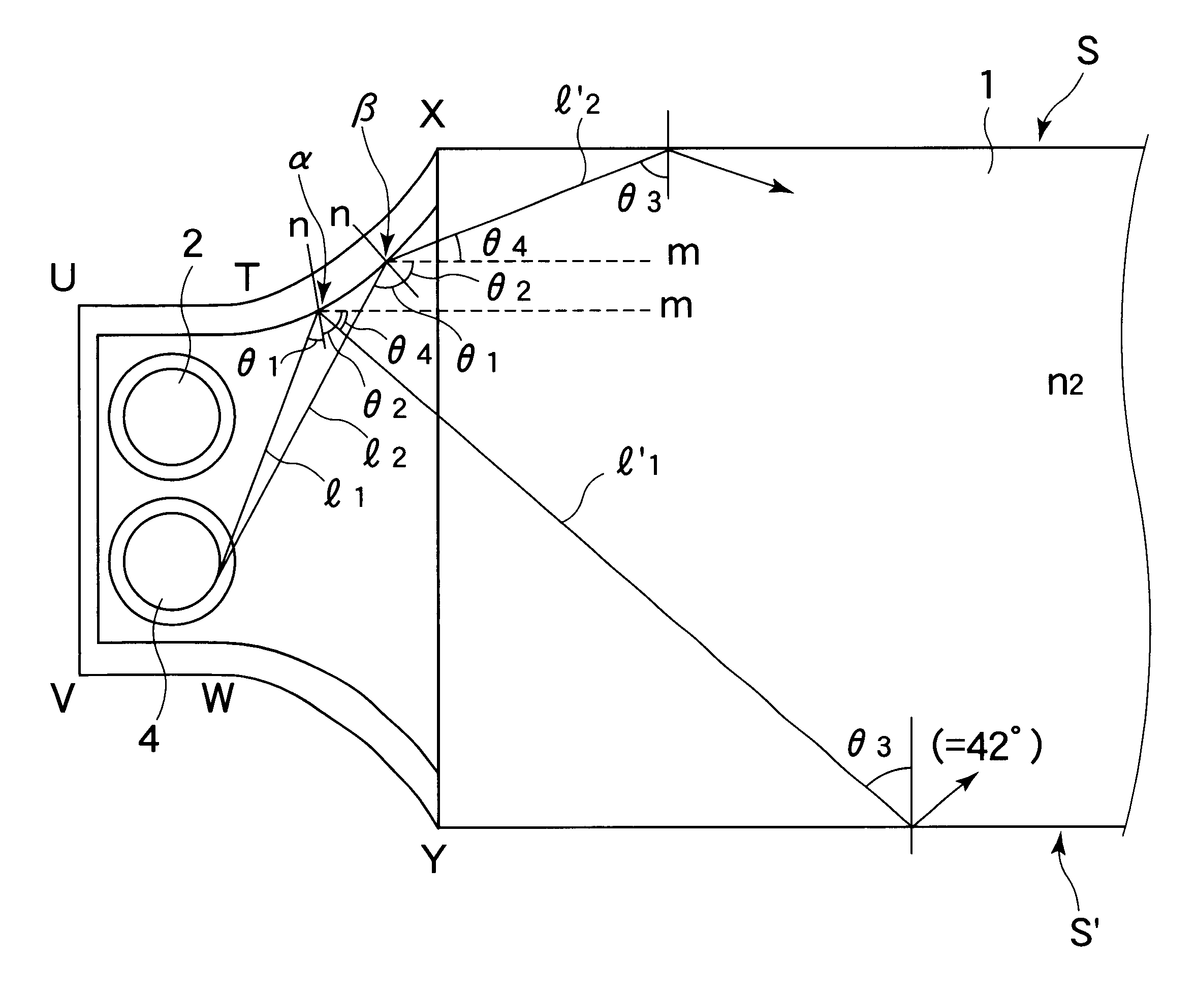
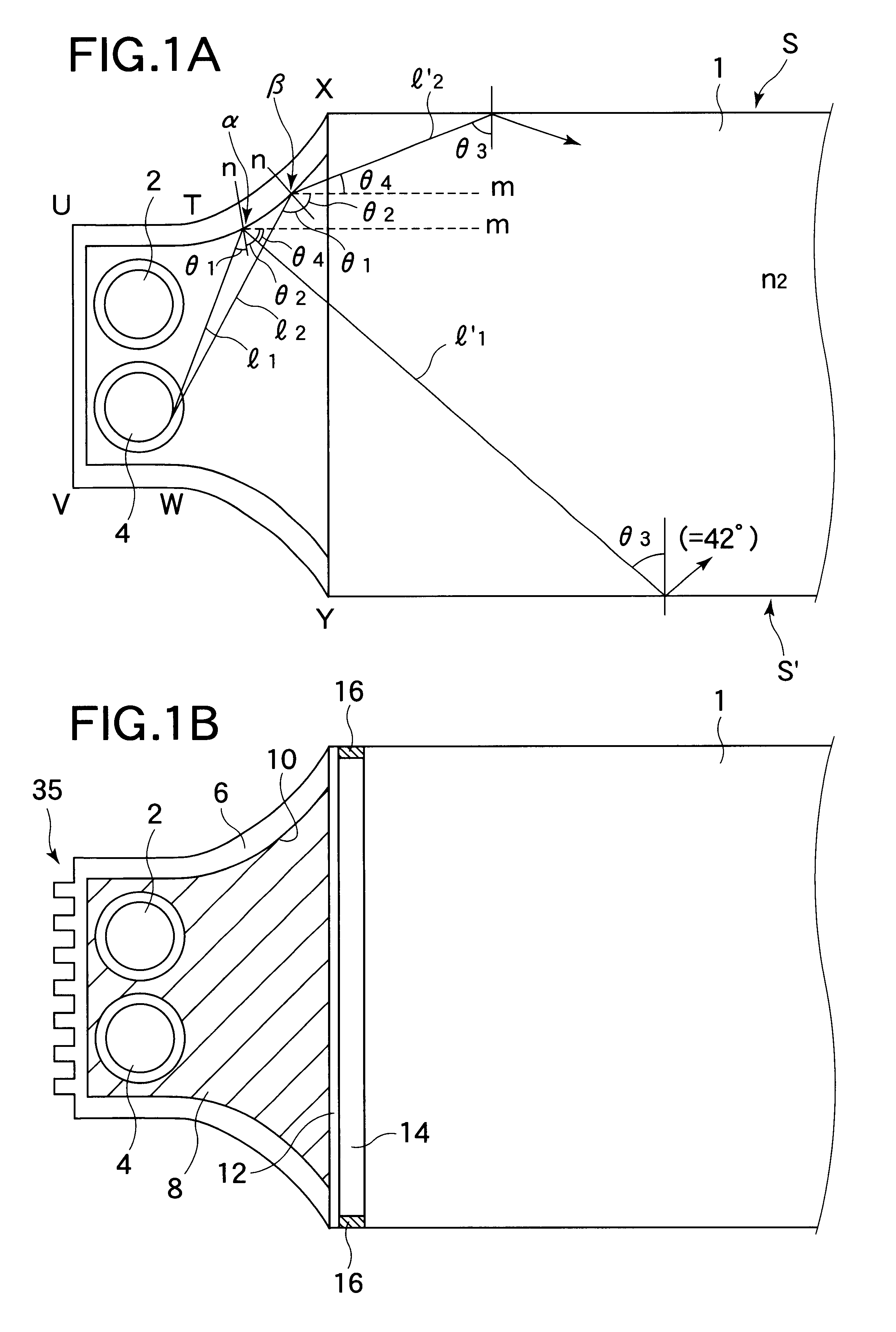
The backlight unit for liquid crystal displays and others of the invention is described with reference to FIG. 1A through FIG. 5. This embodiment provides a backlight unit in which the emitted light is prevented from leaking out of the optical waveguide not undergoing total reflection, even when the light source unit therein is so constituted that the outer peripheral region of each cold-cathode tube therein is filled with a liquid of which the refractive index n1 is nearly the same as the refractive index n0 of the glass material that forms the outer wall of the cold-cathode tube.

In order that a majority of the emitted light can run through the optical waveguide, some methods mentioned below maybe employed. The first method comprises changing the angle of the emitted light in the previous stage before the light enters the optical waveguide so that the light is specifically oriented in the direction falling within the angle range that meets the optical waveguide condition. For examp...

second embodiment

Next described is the backlight unit for liquid crystal displays and others of the invention with reference to FIG. 6 through FIG. 8. This embodiment is to provide a sidelight-type backlight unit in which the light from the cold-cathode tubes can be efficiently reflected toward the optical waveguide.

The backlight unit of this embodiment is characterized in that the reflective surface of the reflector which is disposed opposite to the optical waveguide relative to the cold-cathode tubes and which reflects the light having been emitted toward it from the cold-cathode tubes is so specifically designed that a majority of the light reflected thereon can run toward the space between the cold-cathode tubes adjacent to each other or toward the space between the cold-cathode tubes and the reflector.

In this embodiment, the light emitted by the cold-cathode tubes toward the reflector is, after having been reflected by the reflector, prevented from re-entering the cold-cathode tubes but passes ...

third embodiment

Next described is the backlight unit for liquid crystal displays and others of the invention with reference to FIG. 9 through FIG. 21. This embodiment is to provide a backlight unit enough for practical use even though the light emission efficiency of the cold-cathode tubes therein is low. For this, we, the present inventors have first analyzed the visible ray efficiency from optical viewpoints. As a result, we have found that, in the cold-cathode tubes described hereinabove for the prior art technique with reference to FIG. 43, about 30 to 50% of all the visible light emitted by the phosphor 138 enters the glass tube 136, and the quantity of light that runs outside the glass tube 136 is extremely small, only about 5 to 20% of all.

Specifically, we have found that the light having been reflected on the outer surface of the glass tube 136 (refractive index: 1.5 or so) to go back to the discharge region is almost entirely absorbed by mercury, mercury gas and the phosphor existing there...


PUM

PropertyMeasurementUnit
obtuse angleaaaaaaaaaa
inner diameteraaaaaaaaaa

Abstract

The invention relates to a backlight unit for liquid crystal displays, etc.; and its object is to provide a backlight unit not involving the problem that the emitted light leaks out of the optical waveguide, even when the space around the cold-cathode tubes in the light source unit for it is filled with a liquid of which the refractive index is nearly the same as that of the glass material that forms the outer wall of the cold-cathode tubes. The backlight unit comprises a housing 6 which houses cold-cathode tubes 2, 4 therein and of which the inner surface is coated with a light reflector 10; a transparent liquid filled in the housing 6; and an optical waveguide 1 made of a transparent substance and having a light-emitting surface S. The reflective surface of the light reflector 10 has a cross-section profile of X-T-U-V-W-Y, on which the light emitted by the cold-cathode tubes 2, 4 is reflected, and the thus-reflected light is led to the light-emitting surface S of the optical waveguide 1 at an incident angle not smaller than the critical angle to the surface S.

Description

1. Field of the InventionThe present invention relates to a backlight unit to be used in liquid crystal displays, etc.The invention also relates to a backlight unit in which the light source unit is filled with a transparent liquid.The invention also relates to a reflector structure that realizes high-luminance and high-efficiency sidelight-type backlight units.The invention also relates to a cold-cathode tube usable for a light source that receives essentially the fluorescence of the UV rays having been emitted through discharge emission of mercury or the like and emits visible light, especially for the light source of that type for liquid crystal displays.2. Description of the Related ArtRecently, liquid crystal display panels have been rated highly in the market, as they save space upon installation and save power during operation, and their applications are expanding not only for displays of portable computers and monitors for portable televisions, but also for monitors of desk-...

Claims


Application Information

Patent Timeline
Patent Type & Authority Patents(United States)
IPC IPC(8): G01D11/28F21V8/00G02F1/13357
CPCG01D11/28G02B6/0031G02B6/0036G02B6/0071G02F1/133604G02F1/133606G02F2202/28G02B6/0061
Inventor HAYASHI, KEIJIGOTOH, TAKESHISUZUKI, TOSHIHIROYAMAGUCHI, HISASHIKOBAYASHI, TETSUYAHAMADA, TETSUYASUGAWARA, MARI
Owner SHARP KK
Why Eureka
Try Eureka