Blow mold with removable inserts

a mold and insert technology, applied in the direction of combs, buttons, manufacturing tools, etc., can solve the problems of flash seams, thin layer of material, and the by-product of flash, and achieve the effect of not being desirable in ornamental molded products, and reducing the production cos

Inactive Publication Date: 2003-12-09
TOOLING TECH TOOLING & AUTOMATION
View PDF22 Cites 18 Cited by
  • Summary
  • Abstract
  • Description
  • Claims
  • Application Information

AI Technical Summary

Benefits of technology

The present invention overcomes disadvantages in the prior art by providing an improved mold. The invention provides in one aspect a mold which allows flash seams to be placed in an inconspicuous location comprising two or more mold blocks where a first block has a contact surface, which partially defines the shape of a molded part, a seating surface and a mating surface. A second block half has a contact surface, a sheer surface and a mating surface which abuts the mating surface of the first mold block when the mold is closed. The mold also has removable inserts having contact surfaces, which in conjunction with the mold block contact surfaces define a mold cavity, and having sheer edges which are apposed to the sheer surface of the second mold block. The inserts are seated upon the seating surface of the first mold block and restrict removal of a molded part by overhanging the mold cavity.

Problems solved by technology

One drawback of any molding process is the by-product of flash, a thin layer of material, which is formed within the gap between the mold blocks.
Flash seams may not be desirable in ornamental molded products.
Relocation of flash seams can be difficult depending upon the shape of the molded part and correspondingly, the shape of the interior surface of the mold blocks.
This method has the drawback of still leaving a seam in a conspicuous location.
These inventions do not allow or teach moving the flash seam on a molded product for ornamental reasons.

Method used


Image

  • Blow mold with removable inserts
  • Blow mold with removable inserts
  • Blow mold with removable inserts

Examples


Embodiment Construction

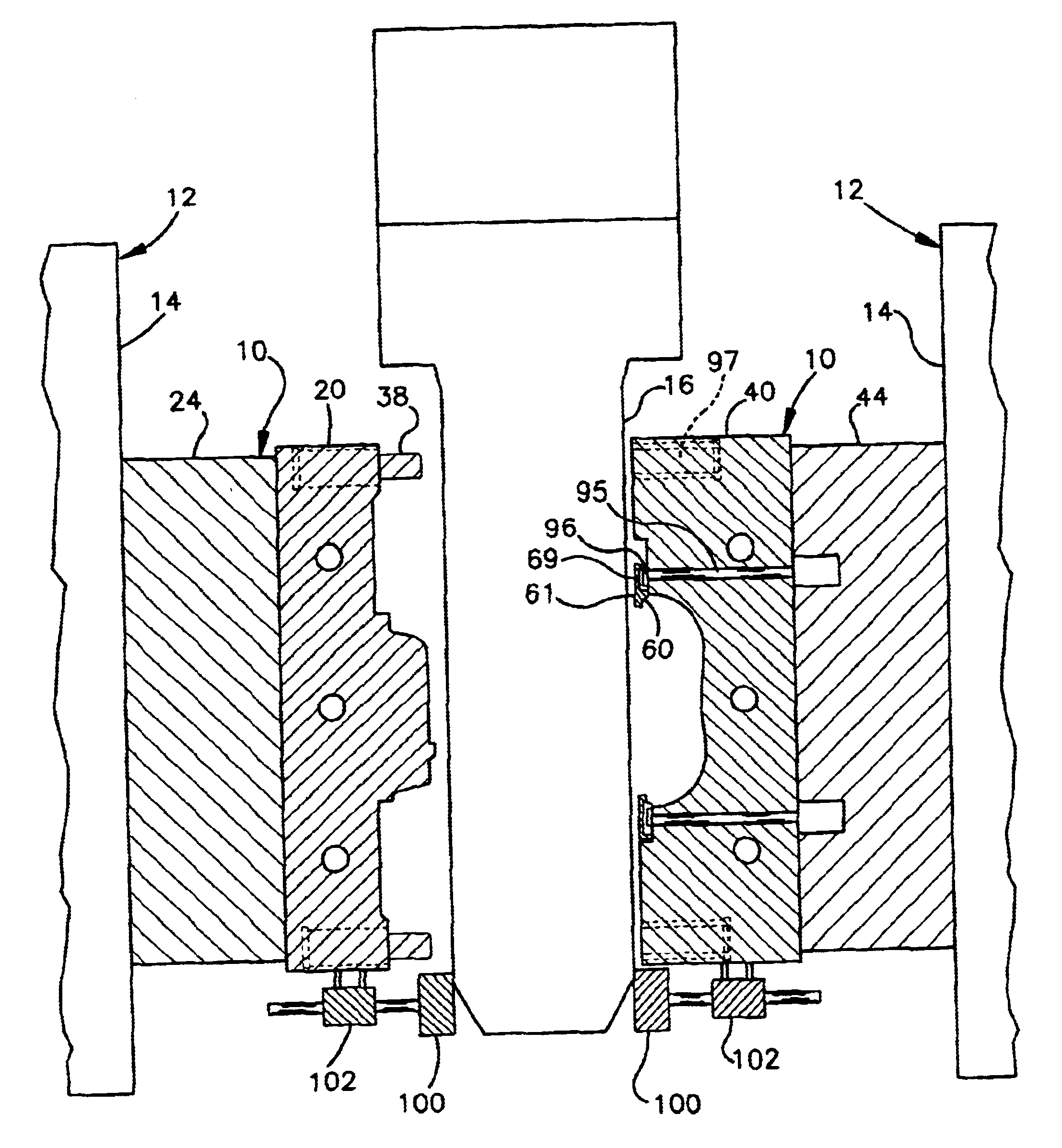
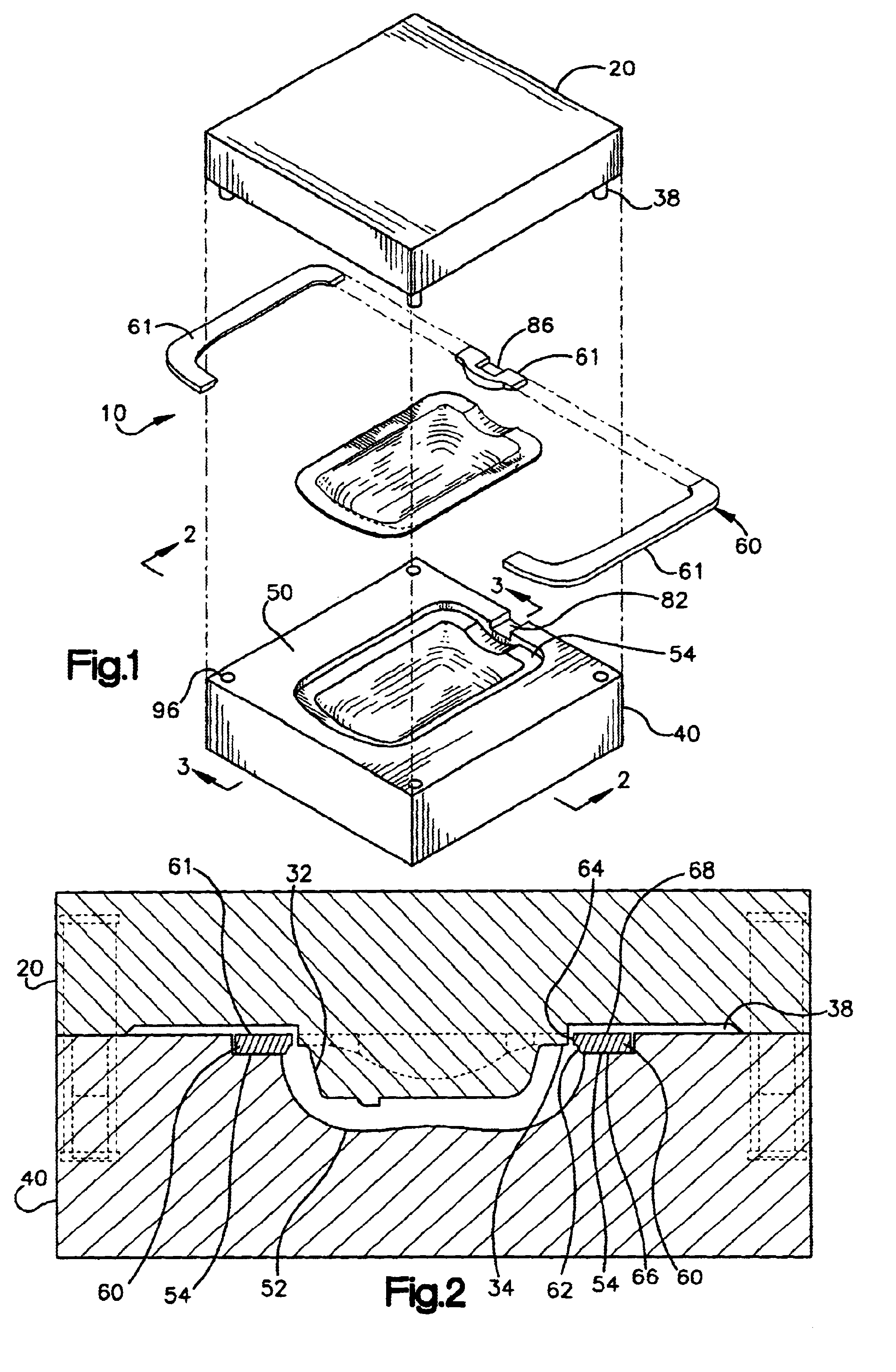
Referring to the drawings, FIG. 1 illustrates a preferred mold 10 according to the invention. The mold 10 is used in combination with a molding machine 12, as shown in FIG. 6, to manufacture molded parts. This mold 10 may be used to create molded parts having flash seams which are inconspicuously located. The mold 10, as described in more detail below, comprises a pin block 20, a bushing block 40, and a removable insert assembly 60. Methods of molding parts using the mold 10 will also be described.

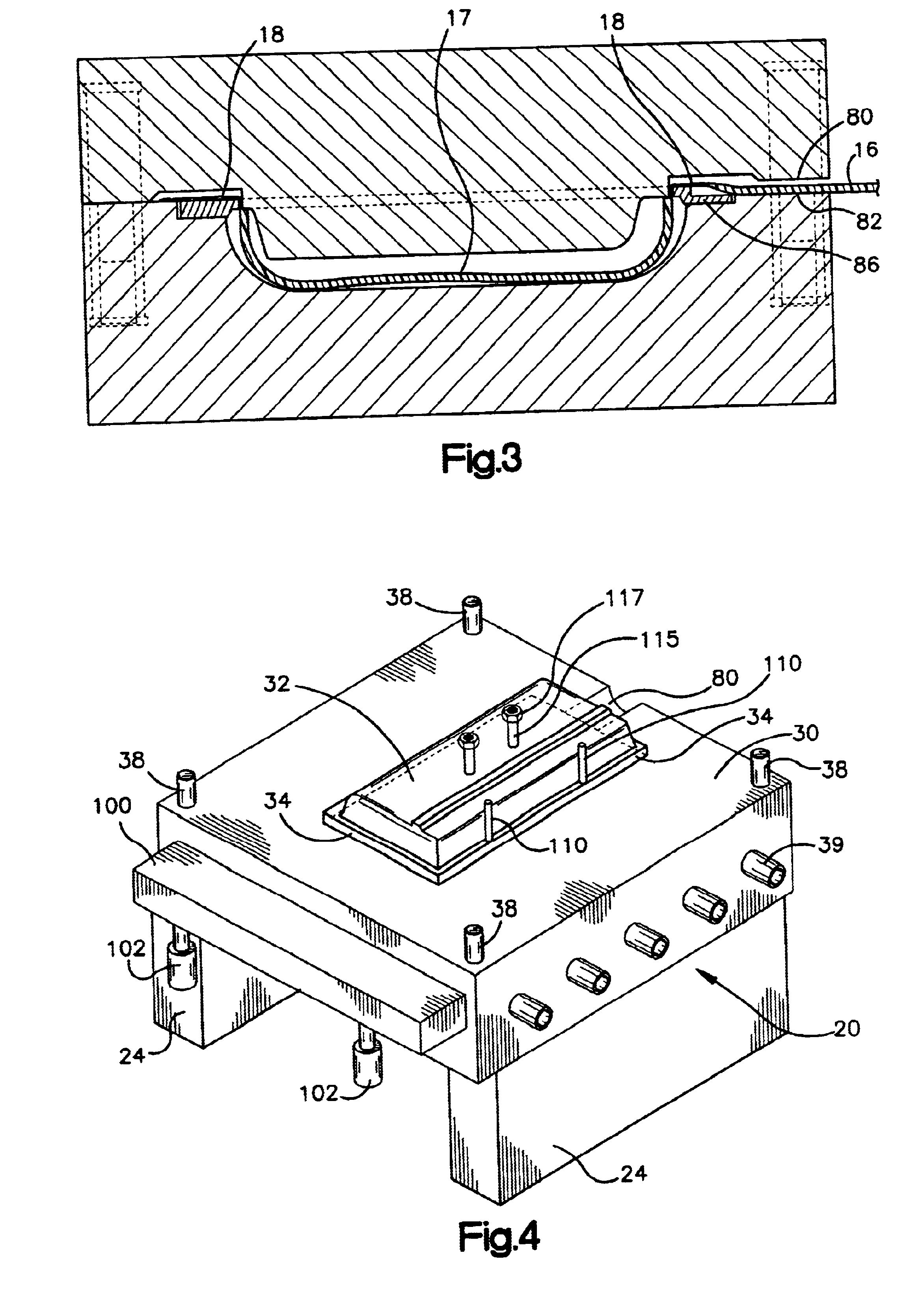
The pin block 20 of the mold 10 is shown in FIG. 4 and has multiple guide pins 38 which align the pin block 20 and bushing block 40 when they are brought together. The pin block 20 is preferably manufactured of aluminum due to considerations of weight, machinability and thermal conductivity, but any material may be used. The pin block 20 is attached to two pin block risers 24, although any number of risers may be used. The pin block risers 24 act as spacers so the mold may be installed in ...


PUM

PropertyMeasurementUnit
displacementaaaaaaaaaa
shapesaaaaaaaaaa
gravityaaaaaaaaaa

Abstract

A mold is provided for forming molded parts having flash seams which are moved to inconspicuous locations. The mold, which is typically used to make blow molded parts, includes two or more mold blocks and removable inserts which allow relocation of flash seams and at the same time allow removal of the finished part from the mold.

Description

This invention relates to molds, more particularly to molds used in blow molding which allow a flashing seam to be moved to an inconspicuous location.Molding is a process used to form substances into desired shapes. Typically a metal or plastic substance, in a fluid state, is placed into a mold by gravity or mechanical force. Most molds consist of two or more blocks, which are separated after the substance has solidified. The finished part is removed from the mold and the molding process is repeated.Plastics may be molded using a variety of processes including blow molding, injection molding, compression molding, transfer molding, and rotational molding. Blow molding is basically a bulging process. A tubular piece of plastic is heated and then pressurized internally and expanded into the cavity of a relatively cool mold. Typical blow molded products are hollow, thin-walled containers or articles.One drawback of any molding process is the by-product of flash, a thin layer of material...

Claims


Application Information

Patent Timeline
Patent Type & Authority Patents(United States)
IPC IPC(8): B29C49/48B29C49/54B29C49/04
CPCB29C49/54B29C49/04B29C49/4823Y10S425/058B29C2049/546Y10S425/033B29C2049/4825
Inventor OVERMYER, SHAWN L.CASS, MARTIN
Owner TOOLING TECH TOOLING & AUTOMATION
Why Eureka
Try Eureka