Active anti-vibration system for cutting tools utilizing piezo-electric elements

a piezoelectric element and anti-vibration technology, applied in the field of active anti-vibration system for cutting tools utilizing piezoelectric elements, can solve the problems of inability to achieve tolerable effects, inability to effectively and inability to control the dampening effect of pure mechanical elements

Inactive Publication Date: 2003-12-09
SANDVIK INTELLECTUAL PROPERTY AB
View PDF9 Cites 11 Cited by
  • Summary
  • Abstract
  • Description
  • Claims
  • Application Information

AI Technical Summary

Benefits of technology

The present invention aims at managing the shortcomings of previously known tools for chip removing machining mentioned in the introduction and at providing a tool with an improved vibration dampening. Thus, a primary object of the invention is to provide a robust tool with the ability to efficiently dampening of vibrations over a wide range of frequencies, for instance where the length of the shank is 3-15 times larger than the diameter thereof, preferably approx. 4-6 times longer than the diameter thereof. It is also an object to provide a tool for chip removing machining having a longer service life for the tool itself as well as the cutting element thereof, compared to previously known tools. Additional objects of the tool are that the use thereof should lead to an increased quality of the surface of the machined workpiece and to an improved working environment by reduction of high frequency noise.

Problems solved by technology

However, this technique works tolerably well only in those cases where the length of the shank is approx.
In addition to this limitation, the pure mechanical dampening has an obvious disadvantage inasmuch as the range of frequencies within which the dampening acts is very limited.
Thus, skis for alpine skiing (K2 Four ski, K2 Corp., USA) have been equipped with piezo-element with the purpose of repressing undesired vibration, which otherwise decreases the contact with the ground and thereby reduces the skier's prospect of a stable and controlled skiing.

Method used


Image

  • Active anti-vibration system for cutting tools utilizing piezo-electric elements
  • Active anti-vibration system for cutting tools utilizing piezo-electric elements
  • Active anti-vibration system for cutting tools utilizing piezo-electric elements

Examples


Embodiment Construction

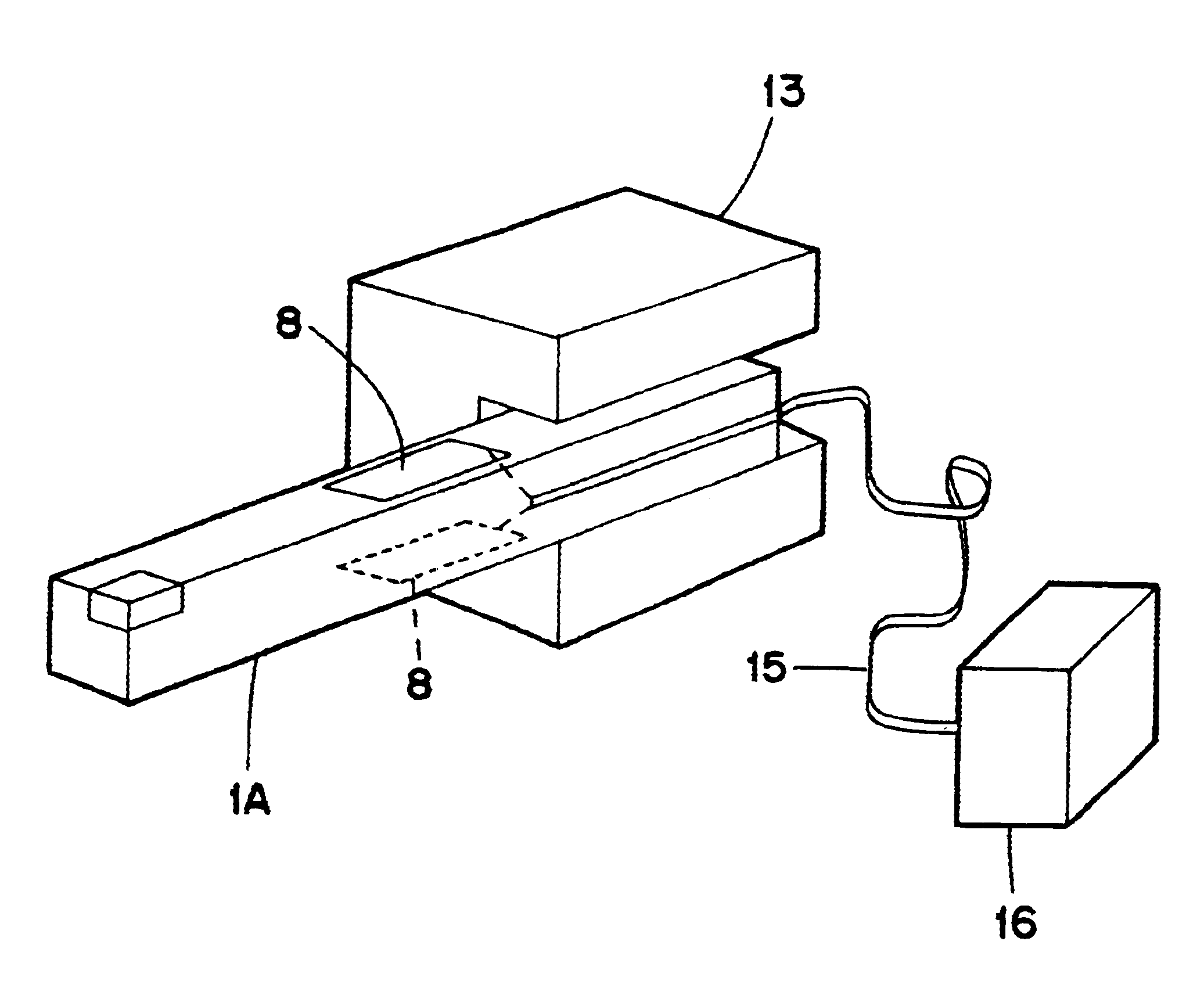
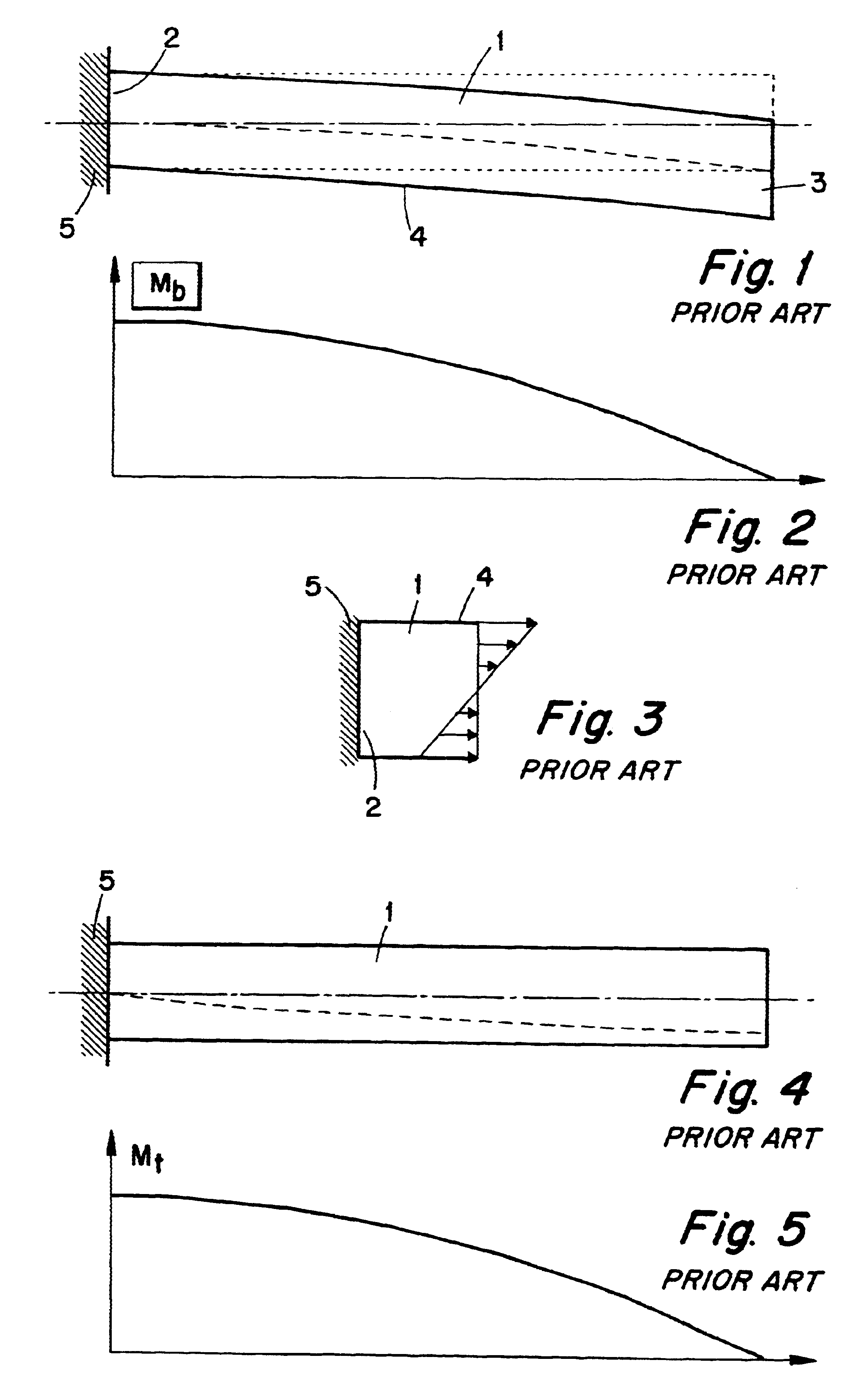
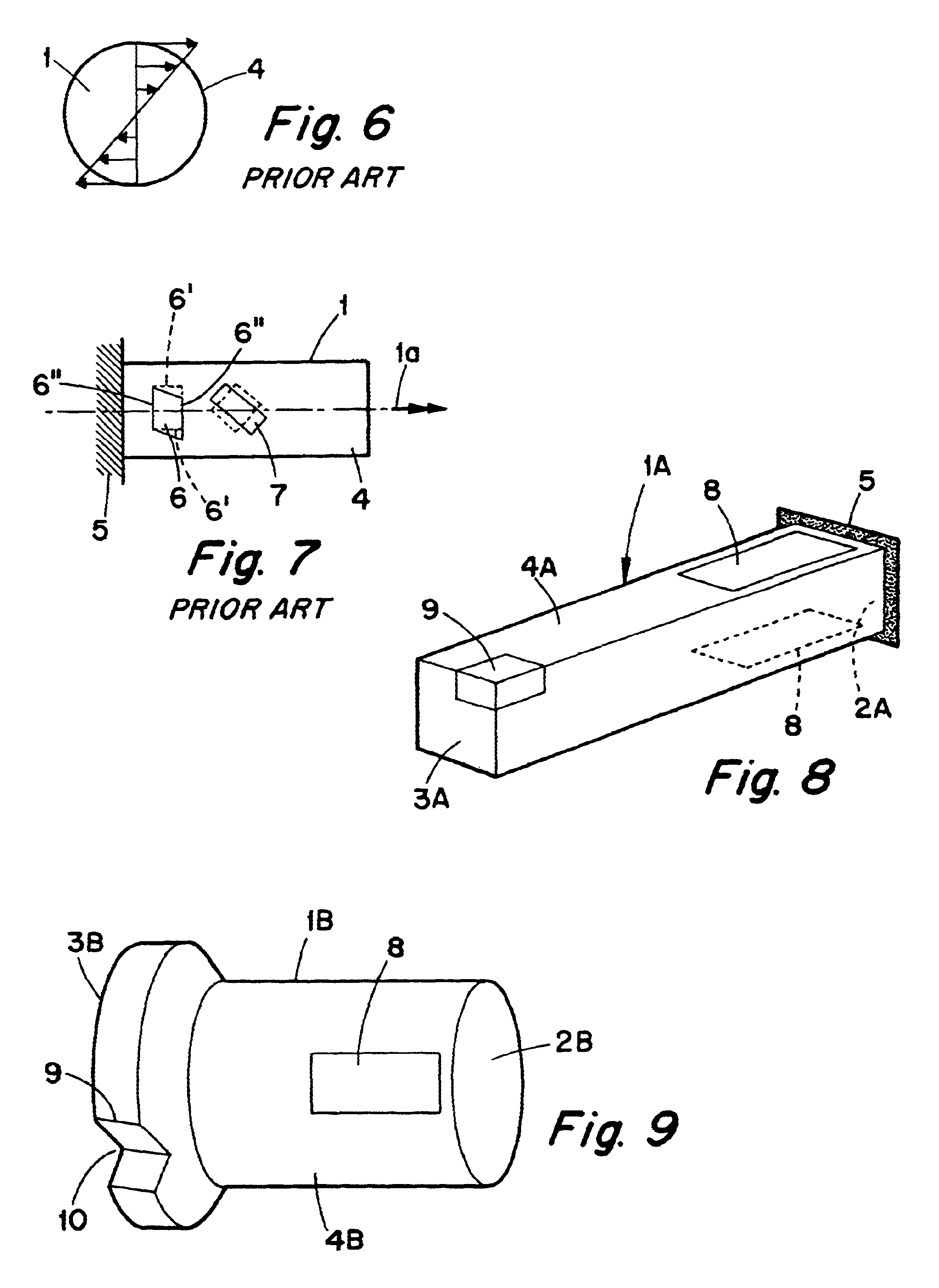
In FIG. 8, a fundamental design of a long narrow tool or shank 1 is shown schematically in which two flat-shaped, rectangular piezo-elements 8 are fastened on opposite, longitudinal plane surfaces 4 of the shank formed with square cross-section. The piezo-elements 8 are placed in the area near the clamping end 2 of the shank. At the outer end 3 thereof, the shank has a machining element in the form of a cutting insert 9. Thus, the piezo-elements 8 are positioned in an area where the largest strain occurs at bending deformation as well as torsional deformation. Although this location is preferred, other locations are also feasible. Furthermore, the piezo-elements 8 are oriented with the major faces thereof essentially parallel to the plane surfaces 4 of the shank and with the major axes essentially parallel to the length extension of the shank 2, and the piezo-elements 8 during bending vibration will be deformed whilst retaining a rectangular shape, while the same at torsional vibrat...


PUM


Abstract

Tool for chip removing machining includes a shank having a clamping end and a cutting insert at an opposite end, plus a number of piezo-elements for dampening vibrations therein. A pair of cooperating, flat-shaped piezo-elements with lengths that are shorter than that of the shank, are placed on opposing sides of the shaft in an area adjacent to the region where the shank is secured in the machine wherein the direction of polarization of the piezo-elements is parallel to the longitudinal axis of the shank. The piezo-elements constitute actuators that are actively steerable through the application of a voltage from a source of electricity via a control device in the form of a logic control circuit, to thereby dampen the bending vibrations of the shank.

Description

This invention relates to a tool intended for chip removing machining of the type that comprises a shank having a clamping end and having a machining element at an opposite end.BACKGROUND TO THE INVENTIONDuring chip removing machining, such as turning or drilling, problems often arise with vibration, specially in cases where the length of the shank or the tool is at least 4-5 times larger than the diameter thereof. One type of vibration is bending vibration, the shank being bent to and fro and submitted to bending deformations. This phenomenon constitutes a common problem, for instance during turning, specially internal turning, where the shank in the form of a boring bar has to be long in order to reach the workpiece, at the same time as the diameter of the bar is limited by the dimension of the hole in which machining is carried out. During such drilling, turning and milling operations, where the distance to the workpiece is large, extension units are used, which frequently cause ...

Claims


Application Information

Patent Timeline
Patent Type & Authority Patents(United States)
IPC IPC(8): F16F15/02F16F15/00B23B27/00B23Q11/00
CPCF16F15/02F16F15/005
Inventor LUNDBLAD, MIKAEL
Owner SANDVIK INTELLECTUAL PROPERTY AB
Why Eureka
Try Eureka