Timing chain lubricating system for engine

a timing chain and lubricating system technology, applied in the field of engine, can solve problems such as difficulty in carrying out appropriate lubrication according to changes

Inactive Publication Date: 2003-12-16
HONDA MOTOR CO LTD
View PDF9 Cites 13 Cited by
  • Summary
  • Abstract
  • Description
  • Claims
  • Application Information

AI Technical Summary

Benefits of technology

In accordance with the above-mentioned arrangement since the operation of the plurality of oil supply means for supplying oil to the timing chain is changed according to the operational state of the engine, lubrication can be carried out according to the operational state of the engine thus reducing the wear of the timing chain.
In accordance with the above-mentioned arrangement, since the oil jet lubricates the section where the sprocket is meshed with the chain on the side that is far from the hydraulic control valve, it becomes easy to supply oil to the section to be lubricated.

Problems solved by technology

In the above-mentioned conventional arrangement, since the oil jet can lubricate only one position of the timing chain, when the amount of oil required and the position that is to be lubricated change according to the operational state of the engine, it is difficult to carry out appropriate lubrication according to the changes.

Method used


Image

  • Timing chain lubricating system for engine
  • Timing chain lubricating system for engine
  • Timing chain lubricating system for engine

Examples


first embodiment

the present invention is explained below by reference to FIGS. 1 to 13.

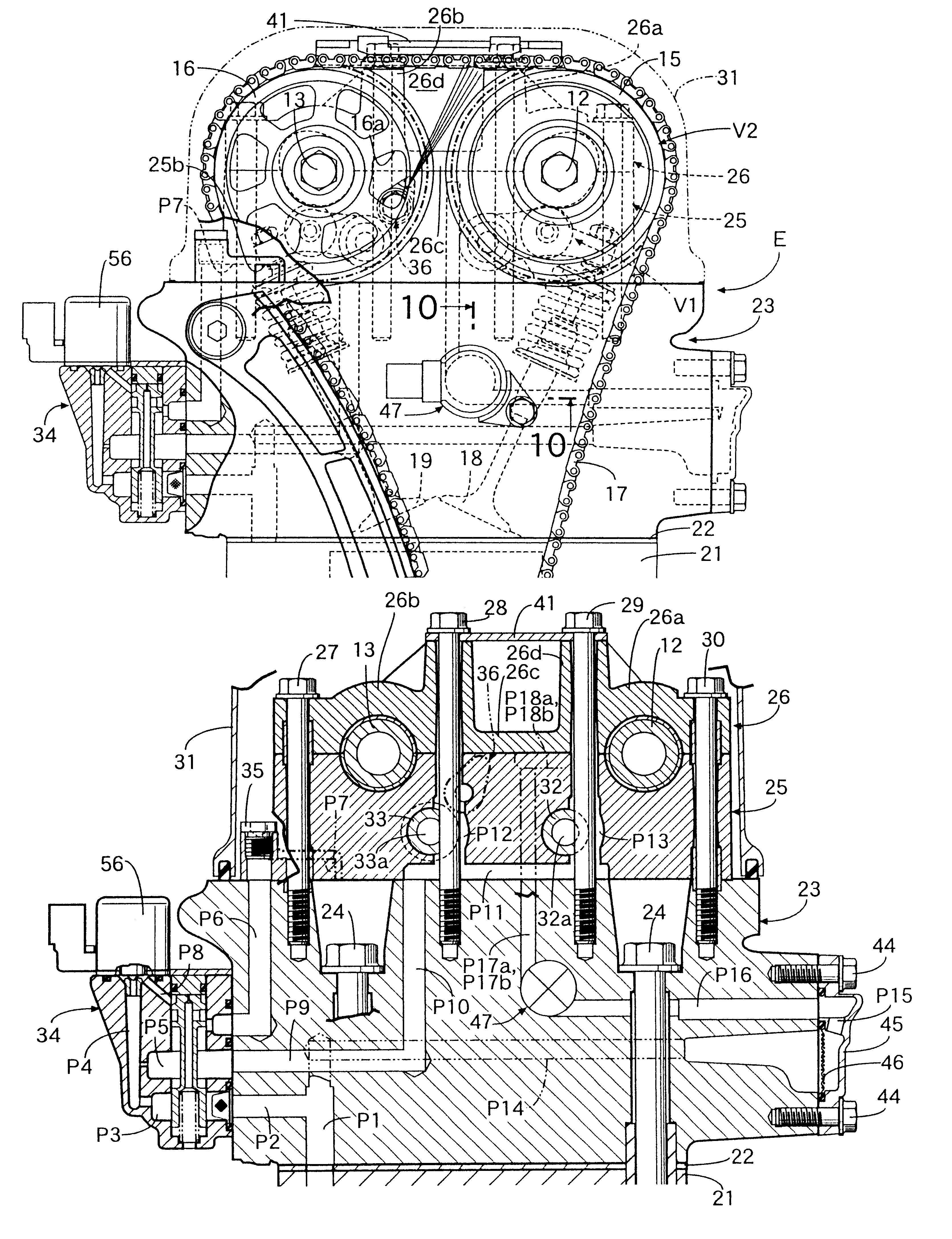
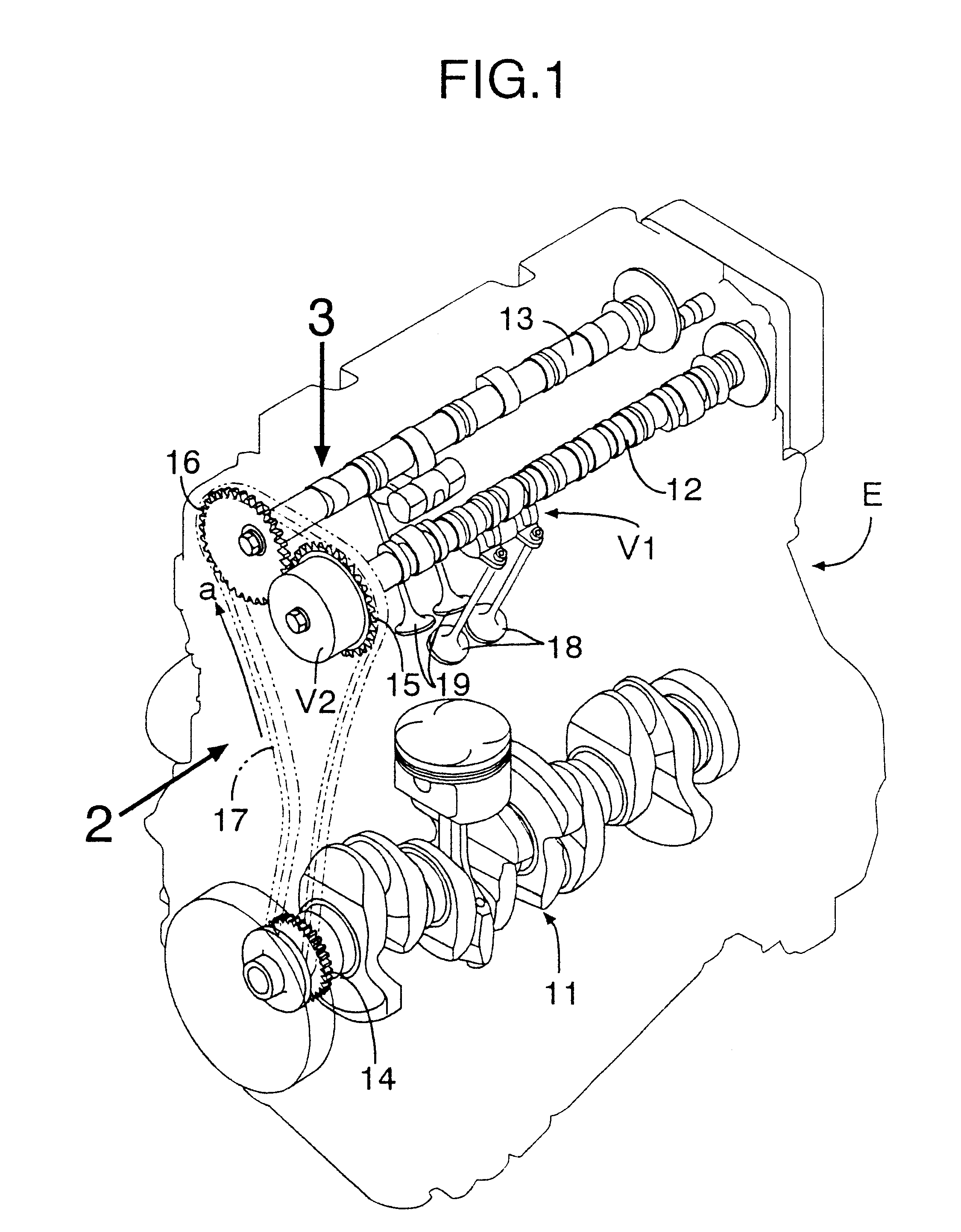
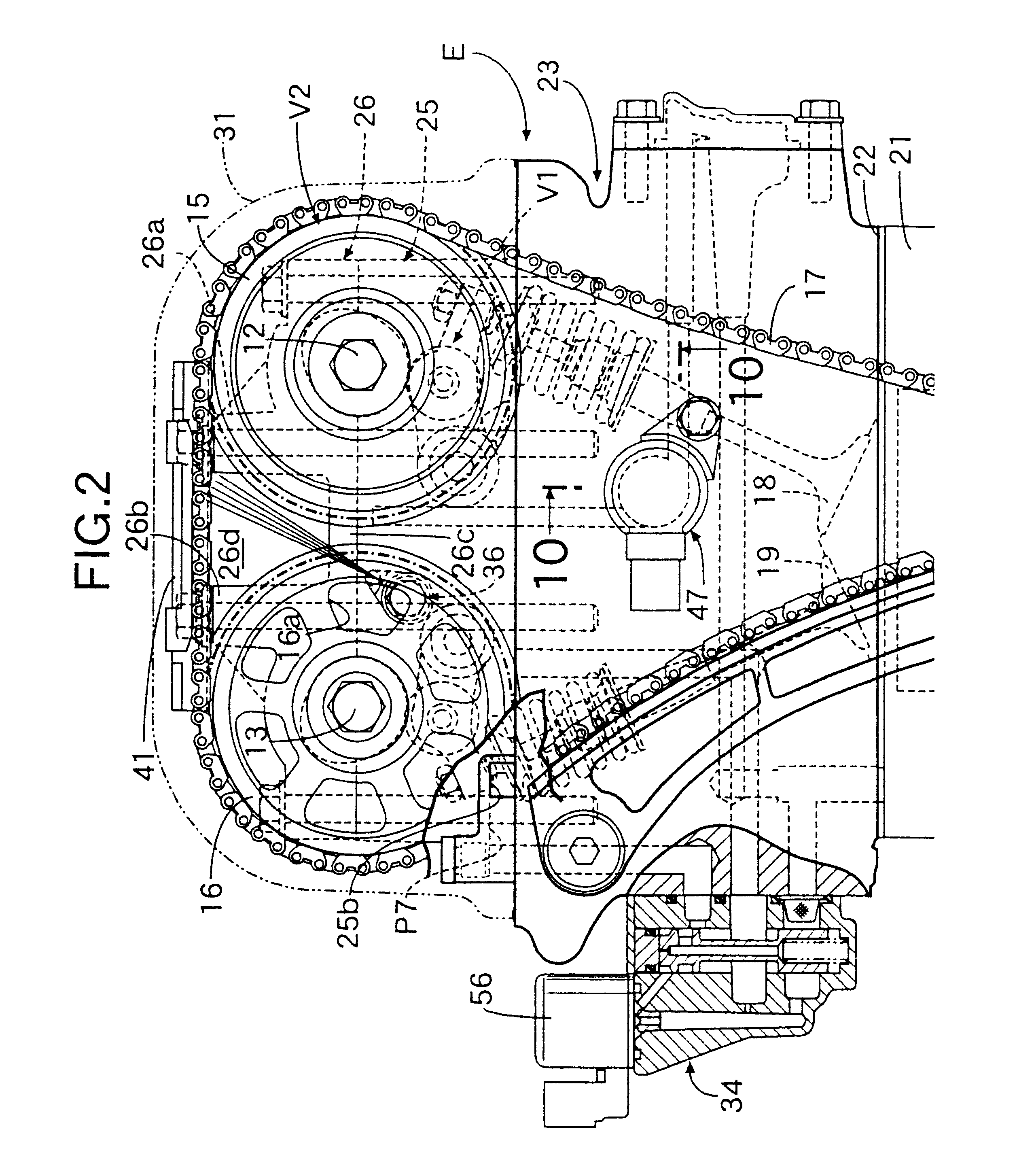
As shown in FIG. 1, a DOHC type in-line four cylinder engine E has a crankshaft 11, an intake camshaft 12 and an exhaust camshaft 13. A timing chain 17 is wrapped around a crankshaft sprocket 14 provided on a shaft end of the crankshaft 11, an intake camshaft sprocket 15 provided on a shaft end of the intake camshaft 12 and an exhaust camshaft sprocket 16 provided on a shaft end of the exhaust camshaft 13. The timing chain 17 is driven in the direction of the arrow a by the crankshaft 11. The intake camshaft 12 and the exhaust camshaft 13 rotate at a speed that is half that of the crankshaft 11. Each of the cylinders has two intake valves 18 driven by the intake camshaft 12 and to exhaust valves 19 driven by the exhaust camshaft 13. The amount of valve lift and the duration for which the valve is open for the two intake valves 18 can be controlled by a first variable valve operating characteristic mechanism V1 pr...

second embodiment

Next, the present invention is explained by reference to FIG. 14.

A chain guide 41 of the second embodiment does not have a sliding member 43 made of a synthetic resin; instead, the upstream side of an oil passage 41a formed within the chain guide 41 communicates with an oil passage P12 formed on the outer periphery of a bolt 28 and the downstream side of the oil passage 41a communicates with an orifice 41c opening on a sliding face 41b facing a timing chain 17. When an engine E rotates at a high speed, and oil at a high pressure is supplied to the oil passage P12, the oil issues toward the inner periphery of the timing chain 17 from an oil jet 36 as well as toward the outer periphery of the timing chain 17, via the orifice 41c, from the oil passage 41a formed within the chain guide 41. A sliding section between the sliding face 41b of the chain guide 41 and the timing chain 17 can be lubricated effectively with the oil issuing through the orifice 41c. It is also possible to make the...


PUM


Abstract

Sprockets are fixed to ends of camshafts supported in a cylinder head via camshaft holders, and a timing chain is wrapped around these sprockets. An oil drain hole is provided for supplying relief oil of a hydraulic control valve to the timing chain, and an oil jet is provided for issuing a jet of oil at high pressure from the hydraulic control valve to the timing chain. When the engine is rotating at low speed oil is supplied only through the oil drain hole, and when the engine is rotating at high speed, oil is supplied through both the oil jet and the oil drain hole. The timing chain wrapped around the sprockets of the camshafts can thereby be reliably lubricated according to the operational state of the engine.

Description

1. Field of the InventionThe present invention relates to an engine in which a sprocket is fixed to one end of a camshaft and a timing chain is wrapped around the sprocket and, in particular, to a timing chain lubricating system therefor.2. Description of the Related ArtA camshaft of an overhead camshaft type engine is driven by an arrangement in which a sprocket fixed to a shaft end of the camshaft is linked to a sprocket fixed to a shaft end of a crankshaft via a timing chain. A lubricating system for such a timing chain is known in Japanese Patent Application Laid-open No, 6-146838. The timing chain lubricating system disclosed in the above-mentioned application has an arrangement in which a relief valve is provided in an oil passage for supplying oil to a hydraulic tappet, and the section where the sprocket is meshed with the chain is lubricated with a jet of oil that issues from an oil jet that is integral with the relief valve,In the above-mentioned conventional arrangement, s...

Claims


Application Information

Patent Timeline
Patent Type & Authority Patents(United States)
IPC IPC(8): F01M9/00F01M9/10F01M1/08F01L1/26F01L1/02F01L1/00F01L1/46F01L1/344F01L1/34F01M1/00F01L13/00F01M1/16
CPCF01L1/02F01L1/022F01L1/267F01L1/34F01L1/3442F01M1/08F01M9/10F01M9/105F01L1/46F02B2275/18F01L2001/0537F01L2001/34426
Inventor KOBAYASHI, TOSHIKI
Owner HONDA MOTOR CO LTD
Why Eureka
Try Eureka