Method of making optical fluoride laser crystal components

a technology of optical fluoride crystal and laser crystal, which is applied in the direction of lapping machines, instruments, polishing compositions, etc., can solve the problems of optical quality pads scratching the surface, the level of final polish currently available is not good enough for optical fluoride crystal laser components, etc., to achieve good polishing effect, reduce flatness, and reduce the effect of flatness

Inactive Publication Date: 2003-12-30
CORNING INC
View PDF4 Cites 2 Cited by
  • Summary
  • Abstract
  • Description
  • Claims
  • Application Information

AI Technical Summary

Benefits of technology

The invention includes a method of making optical fluoride crystal components, preferably optical fluoride crystal laser components and optical lithography systems such as utilized in below 200 nm excimer lasers and optical lithography systems. The method includes providing an optical fluoride crystal having an initial polish finished surface with an initial finish surface roughness greater than 1 nm RMS and an initial finish flatness, providing an optical fluoride crystal final polishing solution, said final polishing solution comprised of a plurality of particulate abrasive agent colloidal silica soot, and polishing with said provided optical fluoride crystal final polishing solution said provided optical fluoride crystal initial polish finished surface to a final polished surface having a reduction in flatness no greater than 50% of said initial finish flatness, and said final polished surface having a final polished surface roughness less than 1 nm RMS. The invention provides a beneficial final polish of 0.5 nm RMS or better to a fluoride crystal that has an initial polished surface less than 5 nm RMS. The polishing solution can be aqueous, preferably in the pH range of 2-12, and more preferably 9-12. In an alternative embodiment the polishing solution is non-aqueous, such as based on ethylene glycol or kerosene. The spherical soot particles provide beneficial polishing of fluoride crystal with little to no scratching and a finer surface finish. The soot particle polish provides better retention of form and figure, and particularly flatness for flat surface optical elements such as laser components, with the belief that the soot particles form a beneficial polishing barrier (due to particle size and size distribution) between the fluoride crystal surface and the polishing pad utilized in the polishing of the fluoride crystal surface. The soot particle polish is preferably applied with a synthetic polishing pad, with the soot providing improved removal rates and preventing damage from polishing pad contact with the fluoride crystal surface, preferably with the soot particles filling the pad pores to form a surface of spherical soot particles that the crystal surface is abraded against.
As such, the pH.sub.PZC values for SiO.sub.2 and TiO.sub.2 --SiO.sub.2 soot particles were determined to be 3.5.+-.0.1 and 2.5.+-.0.1 respectively. The TiO.sub.2 doping of SiO.sub.2 soot increases surface acidity.
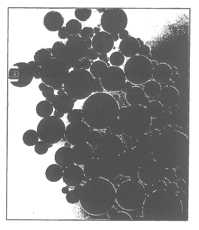
A potential difference in solubility behavior between the soot particles and the parent glasses exists due to the difference in thermal history. With recovery of the fused SiO.sub.2 and TiO.sub.2 --SiO.sub.2 soot particles 32 as a byproduct from the manufacturing process and exhausted from the furnace, the annealing cycle that the glass body boule undergoes in the furnace is not applied to the soot. Research has shown that the annealing process for E-glass lowers the rate of acid corrosion, indicating that glass surfaces become less hydroxylated during annealing. FIGS. 14(c) and (d) demonstrate very similar degree of condensation of soot and glass, the major difference being higher Q.sup.3 component in the .sup.29 Si signal of each soot most likely due to higher OH content caused by much higher surface area of soot 32 compared to glass. The annealing process may also have decreased the OH content of each glass, resulting in a higher surface charge per unit area expected for each soot as compared to the glass surfaces. Thus, the glass surface might show higher corrosion resistance than the soot particles. However, there is no reason to suspect that structural relaxation during annealing affects surface charge results. Thus, the dissociation constants of the SiO.sub.2 soot and TiO.sub.2 --SiO.sub.2 soot materials are believed to be the same for the parent glasses, with the difference in structural relaxation and condensation affecting only the number of surface OH groups which in turn affects the surface reactivity in processes such as corrosion.
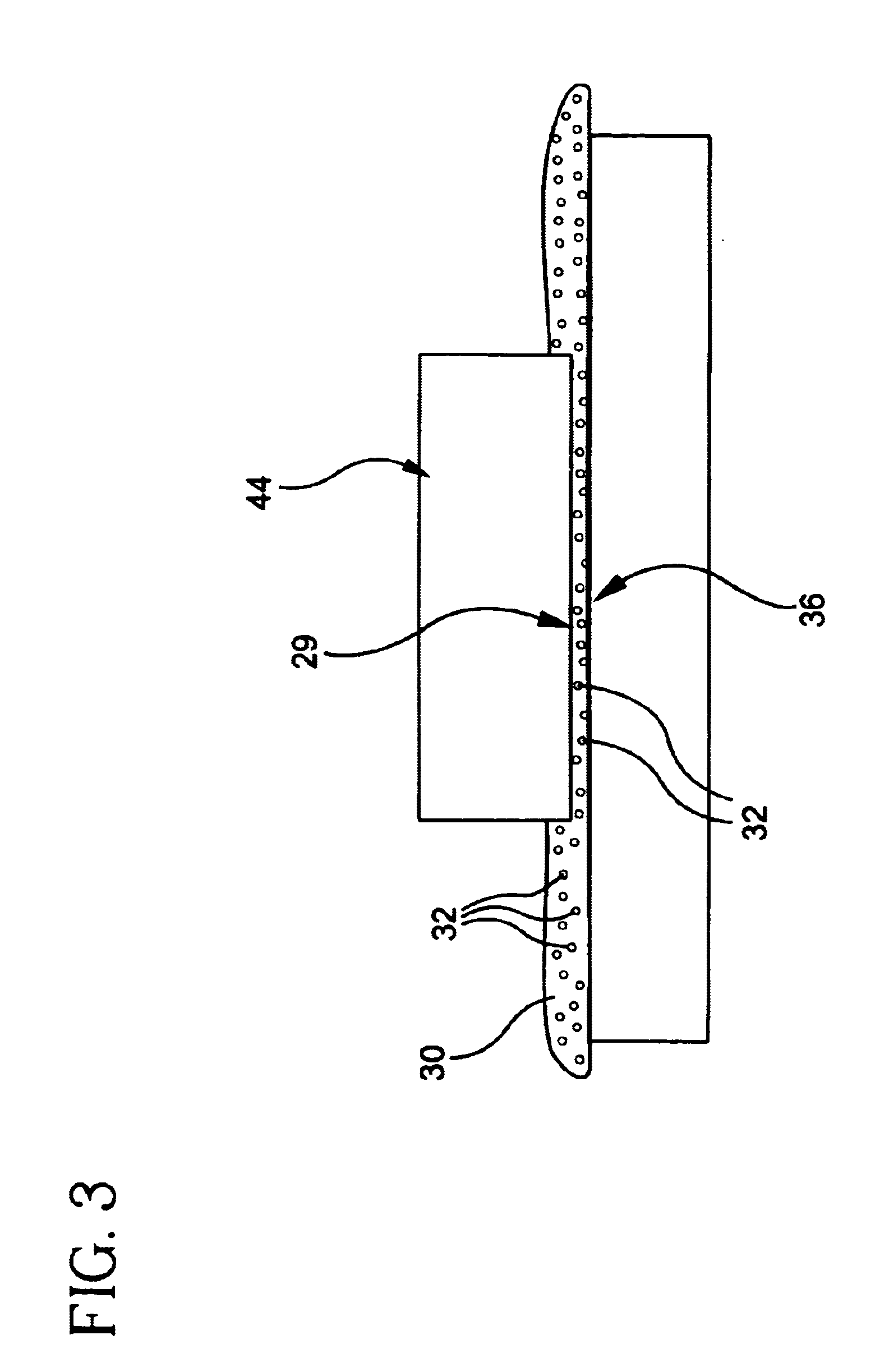
Results show that the inventive fused silica soot particles 32 exhibit greater slurry stability in terms of less agglomeration and / or gellation effects when mixed into a slurry 30. Soot 32 has beneficial lower surface areas, thus promoting lower concentrations of surface charges in solution where particles are mixed to identical weight percents in comparison to fumed silica particles. As a result, the soot 32 can me mixed to greater solids loading (e.g., >10 weight percent) while maintaining lower viscosity values and reflecting Newtonian behavior.
The method of making slurry 30 includes loading at least 1 wt. % of the soot, and more preferably greater than 3 wt. % of the soot in the slurry. Loading at least 1 wt. % preferably includes loading up to 15 wt. % soot into the slurry. With a slurry pH in the range of 1 to 12, more preferably a pH.ltoreq.7, the slurry has stability with loadings in the 3 to 10 wt. % range. The soot slurry 30 has beneficial stability at loadings greater than 3 wt. % as compared to fumed silica slurries, and particularly beneficial 3 and 6 wt. % loadings with low pH's<7. The method includes dispersing a greater than 3 wt. %, preferably 6 wt. %, more preferably 10 wt. % loading of soot wherein the slurry is agglomeration inhibited, gellation inhibited, and has a stabilized viscosity.
The inventive solution is preferably adjusted to a pH that will allow for attainment of the best surface finish, form and figure, and the solution is stabilized from agglomeration and pH shifts during storage.

Problems solved by technology

The level of final polish currently available is not good enough for optical fluoride crystalline laser components.
Also, hard, optical quality pads scratch the surface when used with conventional non-spherical small particle size abrasives.

Method used


Image

  • Method of making optical fluoride laser crystal components
  • Method of making optical fluoride laser crystal components
  • Method of making optical fluoride laser crystal components

Examples


Embodiment Construction

Polishing experiments were as follows. Samples of calcium fluoride crystals were machined via grinding and lapping processes to form a flat surface with minimal subsurface damage with an initially polished surface having a surface finish of about 2.0 nm RMS. Final polishing of the calcium fluoride crystal samples to a 0.5 nm RMS final polished surface with conventional colloidal fumed silica resulted in a 80% reduction in flatness of the samples flat surface. Final polishing of the calcium fluoride crystal samples to a 0.5 nm RMS final polished surface with the inventive colloidal fused silica solid spherical soot resulted in only a 20% reduction in flatness of the samples flat surface.

Solutions preferably prepared from the soot are buffered using a potassium-based solution between pH 10-11. The colloidal silica soot buffered solution can be used in combination with a synthetic soft polishing pad such as Rodel Incorporated's Product Code 204 or Rodel Incorporated's Politex brand pad...


PUM

PropertyMeasurementUnit
surface roughnessaaaaaaaaaa

Abstract

The method of making optical fluoride crystal components provide optical components with beneficial final polished transmission surfaces for transmitting below 200 nm wavelengths of light, such as produced by excimer lasers and utilized in optical lithography. The invention utilizes colloidal silica soot in the polishing of optical fluoride crystal surfaces. This colloidal silica soot is a byproduct of chemical vapor deposition processing of fused silica or ultra low expansion glasses. The colloidal silica byproduct is referred to as "soot". Retaining the same physical properties as the parent glass and having a spherical morphology, the colloidal silica soot is an ideal for final polishing applications of optical fluoride crystals, and particularly for optical fluoride crystals such as calcium fluoride which have high transmission levels to below 300 nm light such as produced by excimer lasers. The soot has a large particle size and spherical shape when compared to conventional colloidal or fumed silica.

Description

The invention relates to optical fluoride crystals, and particularly to optical fluoride crystals, such as calcium fluoride, which have high transmission levels to below 300 nm light, such as produced by excimer lasers. In particular the invention relates to making optical fluoride crystalline laser components with improved flatness final polished surfaces. The invention relates to a calcium fluoride final polishing agent of colloidal silica soot. The invention also relates to a unique method of polishing fluoride crystal optical surfaces using fused silica soot.Applications of colloidal suspensions for polishing materials has become an exceedingly critical aspect of the final part formation of optical components and blanks / preforms thereof. Silica and alumina colloids are formed through various techniques and typically require expensive precursor materials in order to ensure the highest purity products. Solutions are stabilized with buffer systems to pH and solids loading values th...

Claims


Application Information

Patent Timeline
Patent Type & Authority Patents(United States)
IPC IPC(8): B24B13/00B24B1/00B24B7/20B24B7/24C03C19/00C09G1/00C09G1/02C30B33/00G02B1/02B24B37/00B24B57/02
CPCB24B13/00C30B33/00C30B29/12
Inventor SABIA, ROBERT
Owner CORNING INC
Why Eureka
Try Eureka