Transmitting and receiving system for digital communication on electric power-lines

a technology of digital network communication and transmission system, which is applied in the direction of electric controllers, instruments, ignition automatic control, etc., can solve the problems of unavoidable use of complicated circuits and difficult conventional cdma methods

Inactive Publication Date: 2004-01-06
TODA KOHJI
View PDF3 Cites 15 Cited by
  • Summary
  • Abstract
  • Description
  • Claims
  • Application Information

AI Technical Summary

Benefits of technology

Another object of the present invention is to provide a transmitting and receiving system for digital communication on electric power-lines capable of low electric power consumption.
Another object of the present invention is to provide a transmitting and receiving system for digital communication on electric power-lines excellent in durability and manufacturing.
A still other object of the present invention is to provide a transmitting and receiving system for digital communication on electric power-lines having a small size which is very light in weight and has a simple structure.
According to another aspect of the present invention there is provided a bipolar-pulse generator in place of the monopolar-pulse generator. The use of the bipolar-pulse generator enables a high-frequency transmission excellent in transmitting ability on the electric power-lines.
On the other hand, if the first double-coded digital-signal is applied to the left interdigital electrode B.sub.-1 and right interdigital electrode B.sub.1 via the tuning coil, third- and fourth SAWs are excited on the second piezoelectric substrate. The third SAW arrives at the central interdigital electrode B.sub.0 by a time corresponding to the distance L before the fourth SAW arrives at central interdigital electrode B.sub.0. As a result, the first double-coded digital-signal is transduced to a first monocoded burst-signal at central interdigital electrode B.sub.0. The first monocoded burst-signal is transduced to a first monocoded digital-signal at the bipolar-pulse generator. When the first monocoded digital-signal is applied to the second intermediary IDT, a fifth SAW is excited on the second piezoelectric substrate When the fifth SAW corresponds to the third coded pattern, a first decoded pulse is detected at the third coded IDT. In the same way, a second decoded pulse is detected at the fourth coded IDT. As a result, an output digital-signal, which is composed of the first- and second decoded pulses and is equivalent to the message digital-signal, is detected at the detecting terminal via the detecting device. The use of the first- and second electrode-groups enable a double-coding and double-decoding system.
According to a further aspect of the present invention there are provided first- and second electrode-groups. The first electrode-group includes at least two interdigital electrodes A.sub.i {i=1, 2, . . . , (n-1)} at a distance iL {i=1, 2, . . . , (n-1)}, respectively, from the interdigital electrode A.sub.0. The second electrode-group includes at least two right interdigital electrodes B.sub.i {i=1, 2, . . . , (n-1)} at a distance L.sub.0 +iL {i=1, 2, . . . , (n-1)}, respectively, from the central interdigital electrode B.sub.0. When the interdigital electrodes A.sub.i take turns in connecting with the envelope detecting device, the interdigital electrodes B.sub.i take turns in connecting with the receiving connector. The use of the first- and second electrode-groups enable a complicated double-coding and double-decoding system.

Problems solved by technology

However, it is difficult for a conventional type of CDMA method with the SAW matched filter to realize a base-band communication because of a coded message-signal under the condition of a phase shift keying (PSK) burst-signal.
In order to make the digital pulse signal, the use of a complicated circuit is unavoidable for the conventional type of CDMA method with the SAW matched filter.

Method used


Image

  • Transmitting and receiving system for digital communication on electric power-lines
  • Transmitting and receiving system for digital communication on electric power-lines
  • Transmitting and receiving system for digital communication on electric power-lines

Examples


Embodiment Construction

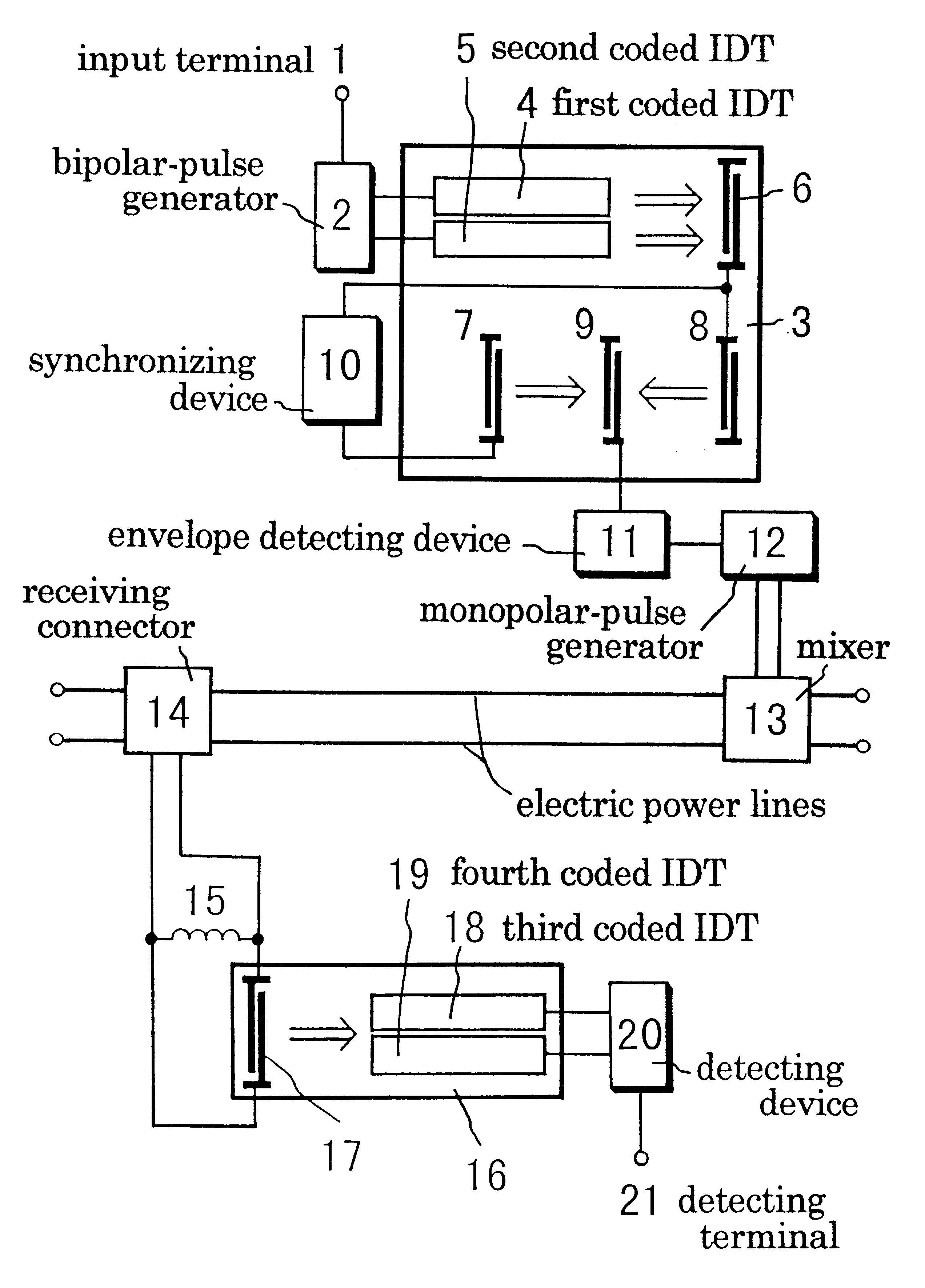
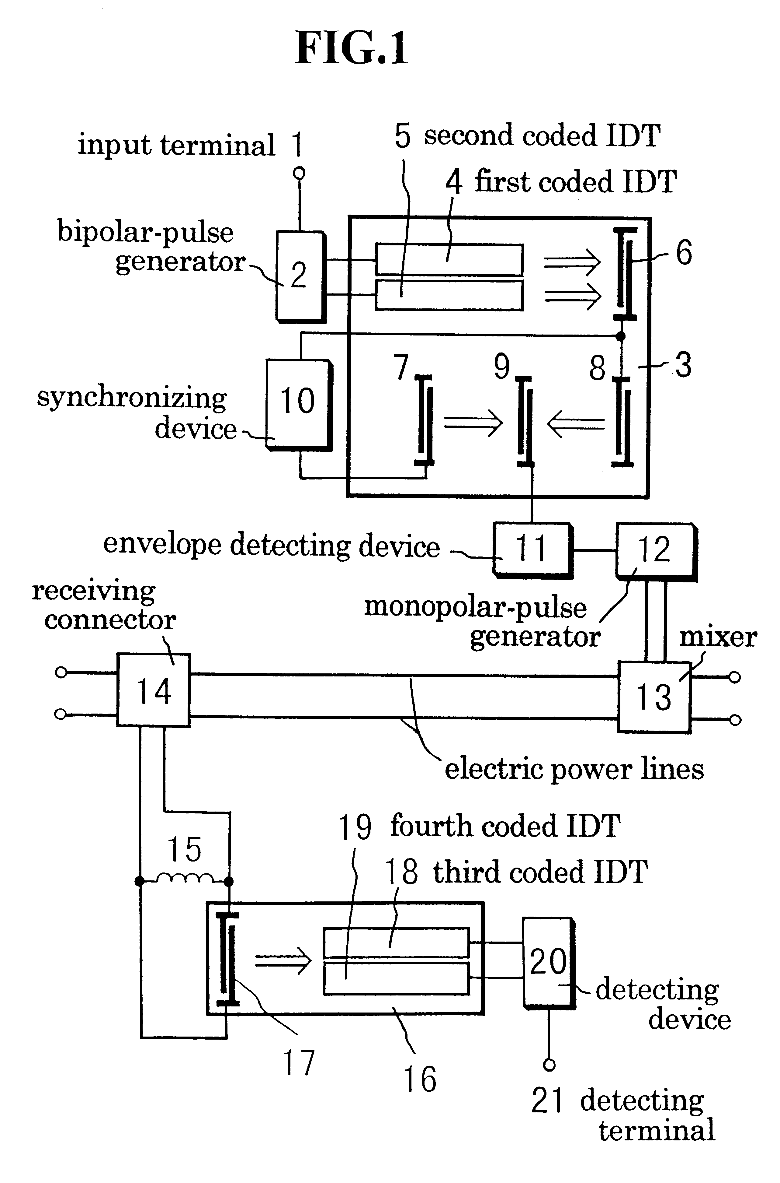
FIG. 1 shows a schematic illustration of a transmitting and receiving system for digital communication on electric power-lines according to an embodiment of the present invention. The transmitting and receiving system for digital communication on electric power-lines comprises transmitting-and receiving devices. The transmitting device comprises input terminal 1, bipolar-pulse generator 2, first piezoelectric substrate 3, first coded IDT 4, second coded IDT 5, first intermediary IDT 6, sideward IDT 7, sideward IDT 8, central IDT 9, synchronizing device 10, envelope detecting device 11, monopolar-pulse generator 12, and mixer 13 connected with electric power-lines. Sideward IDT 7, sideward IDT 8, and central IDT 9 form an electrode group. Synchronizing device 10 is connected between first intermediary IDT 6 and sideward IDT 7. Envelope detecting device 11 is connected with central IDT 9. The receiving device comprises receiving connector 14 connected with the electric power-lines, tu...


PUM


Abstract

A transmitting and receiving system for digital communication on electric power-lines comprises a transmitting device and a receiving device. The transmitting device consists of an input terminal, a bipolar-pulse generator, a first piezoelectric substrate, first- and second coded IDTs, a first intermediary IDT, an electrode group, a synchronizing device, an envelope detecting device, a monopolar-pulse generator, and a mixer connected with electric power-lines. The receiving device consists of a receiving connector connected with the electric power-lines, a tuning coil, a second piezoelectric substrate, a second intermediary IDT, third- and fourth coded IDTs, a detecting device, and a detecting terminal. If a message digital-signal is applied to the bipolar-pulse generator via the input terminal, high-frequency bipolar-pulses (-1 and 1) are generated, and after all, are transduced to first- and second coded digital-signals at the monopolar-pulse generator. The first- and second coded digital-signals are delivered into the electric power-lines via the mixer. On the other hand, if the first coded digital-signal is received at the receiving connector, the first coded digital-signal is applied to the second intermediary IDT via the tuning coil. The first coded digital-signal is, after all, transduced to a first decoded pulse at the third coded IDT. In the same way, the second coded digital-signal is transduced to a second decoded pulse at the fourth coded IDT. As a result, an output digital-signal, which is composed of the first- and second decoded pulses and is equivalent to the message digital-signal, is detected at the detecting terminal via the detecting device.

Description

1. Field of the InventionThe present invention relates to a transmitting and receiving system for digital network communication on electric power-lines by means of using transmitting- and receiving devices, of which each includes a piezoelectric substrate and two coded interdigital transducers (IDTs).2. Description of the Prior ArtElectric power-lines are greatly desired to be used for digital network communication. If a code division multiple access (CDMA) method avails for digital communication on electric power-lines, it is possible to make a transmission speed, in spread spectrum communication, high. In addition, if a surface acoustic wave (SAW) matched filter is incorporated in the CDMA method, it is possible to make the transmission speed still higher. However, it is difficult for a conventional type of CDMA method with the SAW matched filter to realize a base-band communication because of a coded message-signal under the condition of a phase shift keying (PSK) burst-signal. I...

Claims


Application Information

Patent Timeline
Patent Type & Authority Patents(United States)
IPC IPC(8): H04B3/54
CPCH04B3/54H04B2203/5412H04B2203/5483
Inventor TODA, KOHJI
Owner TODA KOHJI
Why Eureka
Try Eureka