Method and device for synchronizing and testing a processor and a monitoring circuit

Inactive Publication Date: 2004-01-06
ROBERT BOSCH GMBH
View PDF13 Cites 13 Cited by
  • Summary
  • Abstract
  • Description
  • Claims
  • Application Information

AI Technical Summary

Problems solved by technology

If these have a monitoring circuit in the standard manner, then a n

Method used


Image

  • Method and device for synchronizing and testing a processor and a monitoring circuit
  • Method and device for synchronizing and testing a processor and a monitoring circuit
  • Method and device for synchronizing and testing a processor and a monitoring circuit

Examples


Embodiment Construction

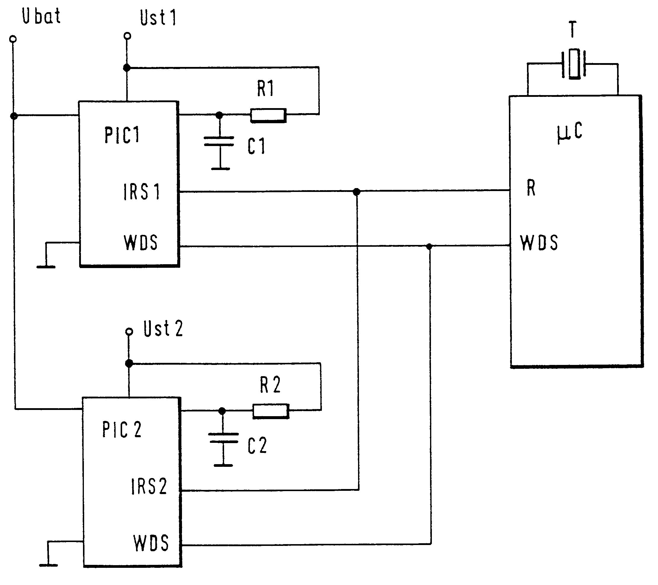
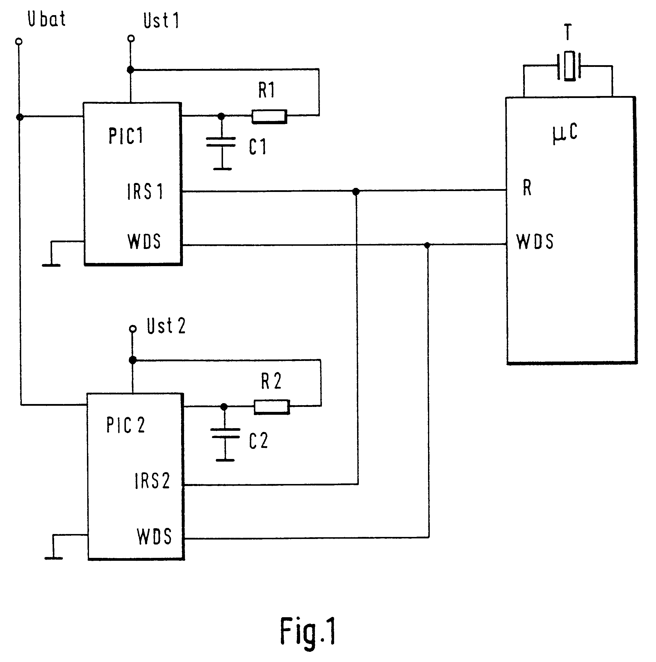
FIG. 1 shows a preferred exemplary embodiment of a circuit of a microcontroller .mu.C and two peripheral components PIC1 and PIC2, which each contain at least one watchdog circuit The two peripheral components PIC1 and PIC2 are, for example, ASICS in the triggering device for triggering an airbag. In this instance, the entire circuit from FIG. 1 can be integrated into the triggering device. A timing generator for the microcontroller .mu.C is labeled T. This can, for F) example, be a vibrating quartz crystal. The two peripheral components PIC1 and PIC2 are connected to the reset input R of the microcontroller .mu.C via a reset line. In this particular example, this reset line is designed as a high line. This means that normally, a high signal level is present at the reset Input R of the microcontroller .mu.C and a reduction of this high level to a low signal level, in particular, to ground, triggers a reset. This takes place by means of the signals of the pulse reset outputs IRS1 and...


PUM


Abstract

The invention relates to a method and apparatus for synchronizing at least one computer, having at least one monitoring circuit associated with this computer. The synchronization takes place through at least one transmitted signal (WDS) in the form of a double pulse from the computer (muC) to the peripheral components (PIC1, PIC2), which contain the monitoring circuits. To that end, shortly after the computer (muC) is started up at system start or after an HW reset, the signal (WDS) is sent to the at least one peripheral component (PIC1, PIC2). After this, the upper and lower limit of the signal sequence (WDS) to be regularly transmitted by the computer for the monitoring circuit are tested and therefore the function of the monitoring circuits is tested. As with the synchronization, the testing takes place with a reaction of the monitoring circuits by means of at least one acknowledgement signal (IRS1, IRS2, R).

Description

PRIOR ARTThe invention relates to a method and apparatus for synchronizing and checking at least one processor and at least one associated monitoring circuit according to the preambles to the claims.DE 35 39 407 A1 has disclosed a computer system with two processors in which during normal operation, the computing workload is evenly distributed to the two processors and in the event that one of the processors malfunctions, the other processor switches into a corresponding emergency function. In order to detect malfunctions, each processor is associated with precisely one monitoring circuit. A synchronization of the monitoring circuit with the processor is not provided, nor is the association of a number of monitoring circuits with one processor.This kind of monitoring circuit, also referred to as a watchdog, is disclosed in many ways in the prior art, e.g. also in DE 40 23 700 A1. In this instance, a watchdog signal that is transmitted by the processor at regular chronological interv...

Claims


Application Information

Patent Timeline
IPC IPC(8): G06F11/00G06F11/267G06F11/16G06F11/30
CPCG06F11/0757G06F11/2215G06F11/1675
Inventor SCHUMACHER, HARTMUTRINGGER, KLAUS
Owner ROBERT BOSCH GMBH
Why Eureka
Try Eureka