Filter trimming

a filter and filter technology, applied in the direction of pulse manipulation, pulse technique, line-transmission details, etc., can solve the degree of uncertainty with respect to the component values of specific component types, power losses, and introduce a degree of distortion into the signal path

Inactive Publication Date: 2004-02-03
NAT SEMICON CORP
View PDF7 Cites 38 Cited by
  • Summary
  • Abstract
  • Description
  • Claims
  • Application Information

AI Technical Summary

Benefits of technology

The invention thereby provides an efficient solution, which makes it possible to handle unavoidable process variations of integrated component values.
The invention also offers a competent possibility for continuous compensation for any variations in component values due to temperature variations.

Problems solved by technology

The manufacturing process for integrated circuits generally causes a degree of uncertainty with respect to the component values of specific component types.
Digital filters, however, always cause power losses and introduce a degree of distortion into the signal path.
Digital filters are therefore undesired if they can be avoided.
However, the solution involves active filters that per se are relatively noisy and non-linear.
This in turn causes distortion and deteriorates the filter performance, which of course, is adverse.
However, the proposed solutions are associated with various unwanted side effects, such as power loss, distortion, noise or combinations thereof.
Moreover, the proposed solution includes standardised and relatively uncomplicated building blocks.

Method used


Image

  • Filter trimming
  • Filter trimming
  • Filter trimming

Examples


first embodiment

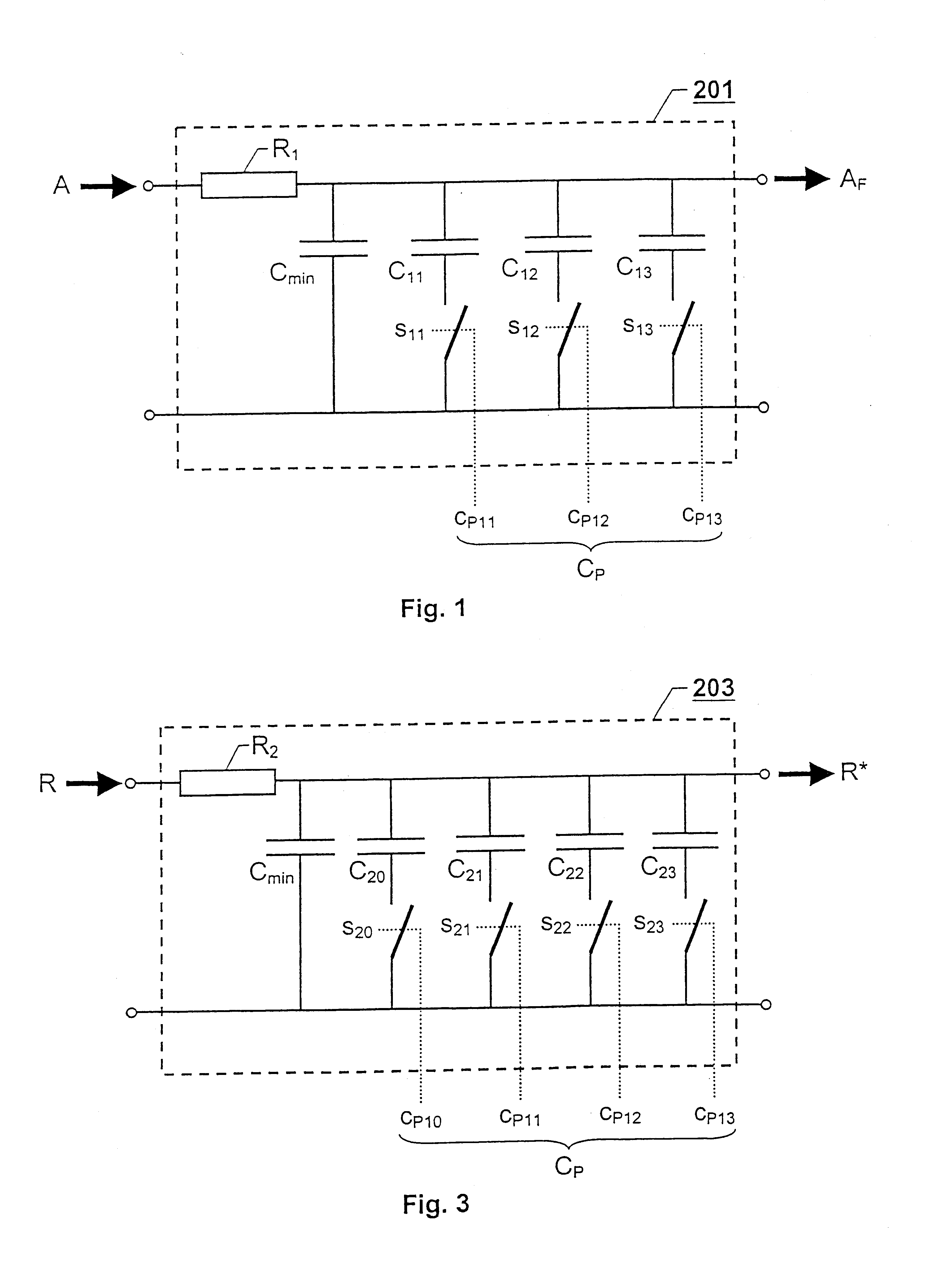
FIG. 3 shows a circuit diagram over an adjustable phase shifter according to the invention. As can be seen in the figure, the adjustable phase shifter 203, in similarity with the analogue lowpass filter 201, contains a set of controllable switches s.sub.20, s.sub.21, s.sub.22 and s.sub.23, which each controls a particular capacitor C.sub.20, C.sub.21, C.sub.22 and C.sub.23 respectively, such that any combination of individual capacitors C.sub.20 -C.sub.23 may be included electrically in a filter circuit in addition to the minimum capacitance C.sub.min. The state of each controllable switch s.sub.20 -s.sub.23 is in turn determined by the value of the signal elements c.sub.P10 -c.sub.P13 in the control signal C.sub.P.

Depending on the number of controllable switches s.sub.20, s.sub.21, s.sub.22 and s.sub.23 in the adjustable phase shifter 203, the signal elements c.sub.P10 -c.sub.P13 may be arranged according to a particular number of different combinations. The control signal C.sub.P ...

second embodiment

FIG. 4 shows a circuit diagram over an analogue filter according to the invention, wherein both a resistance value and a capacitance value can be altered. In the illustrated example, the control signal C.sub.P has six signal elements c.sub.P11 -c.sub.P16, of which the first three c.sub.P11 -c.sub.P13 control a respective switch s.sub.11 -s.sub.13 for a particular resistor R.sub.11 -R.sub.13. All the resistors R.sub.11 -R.sub.13 are coupled in parallel with a fix resistor R.sub.max, such that the total resistance value can be varied from (R.sub.max.sup.-1 +R.sub.11.sup.-1 +R.sub.12.sup.-1 +R.sub.13.sup.-1).sup.-1 to R.sub.max. Correspondingly, the last three signal elements c.sub.P14 -c.sub.P16 in the control signal C.sub.P control a respective switch s.sub.14 -s.sub.16 for a particular capacitor C.sub.14 -C.sub.16 being coupled in parallel with a fix capacitor C.sub.min, such that the total capacitance value can be varied from C.sub.min to (C.sub.min +C.sub.14 +C.sub.15 +C.sub.16). ...


PUM


Abstract

The invention relates to trimming of analogue filters (201) in integrated circuits by means of an automatic adjusting circuit. A local oscillator (202) in the automatic adjusting circuit provides a periodic reference signal (R) to an adjustable phase shifter (203), which on basis thereof, produces a periodic phase shifted signal (R*). A phase detector (204) receives both the periodic reference signal (R) and the phase shifted period signal (R*) and produces a test signal (T) in response to a phase difference between the periodic reference signal (R) and the periodic phase shifted signal (R8). A lowpass filter (205) receives the test signal (T) and generates a level signal (TDC) relative a reference level, e.g. representing a zero voltage. A digital signal processor (207) produces a primary control signal (CS), having a serial format, on basis of the observation signal (M). A serial-to-parallel converter (208) converts the primary control signal (CS) into a control signal (CP) having a parallel signal format. The control signal (CP) influences a magnitude of at least one component value in the adjustable phase shift between the periodic reference signal (R) and the periodic phase shifted signal (R*) attains a calibrated value being as close as possible to a desired value. A latch (210) forwards at least one signal element of the control signal (CP) for setting of at least one component value in the analogue filter (201) in accordance with a setting of at least one component value in the adjustable phase shifter (203) which produces the calibrated value.

Description

THE BACKGROUND OF THE INVENTION AND PRIOR ARTThe present invention relates generally to trimming of analogue filters in integrated circuits. More particularly, the invention relates to a method for automatically altering a magnitude of at least one component value in an analogue filter and an automatic adjusting circuit for calibrating an analogue filter in an integrated circuit. The invention also relates to a computer program and a computer readable medium.The manufacturing process for integrated circuits generally causes a degree of uncertainty with respect to the component values of specific component types. Integrated passive components, such as capacitors and resistors demonstrate undesirable variations in component values, so-called process variations. The value of an actual RC-product in a filter may deviate as much as 30-40% from a nominal value as a consequence of the process variations. Various attempts have already been made to compensate for these detrimental effects.Fo...

Claims


Application Information

Patent Timeline
Patent Type & Authority Patents(United States)
IPC IPC(8): H03H11/04H03L7/08H03H11/12H03L7/081
CPCH03H11/1291H03L7/0805H03L7/0814H03J2200/07H03J2200/10H03J2200/18H03L7/0816
Inventor NYSTROM, CHRISTIANKONRADSSON, PERGRASBECK, ARI
Owner NAT SEMICON CORP
Why Eureka
Try Eureka