
Distributed switch memory architecture

a switch memory and switch technology, applied in the field of network switching, can solve problems such as packet transmission delay, unsatisfactory performance, and blockage of head of lin

Inactive Publication Date: 2004-02-24
INTEL CORP
View PDF7 Cites 37 Cited by
  • Summary
  • Abstract
  • Description
  • Claims
  • Application Information

AI Technical Summary

Benefits of technology

Another object of the invention is to provide a switch system that can easily incorporate advances in DRAM technology (e.g., higher speed, higher bandwidth or higher capacity).
Another object of the invention is to provide a switch system capable of higher integration and lower implementation costs as compared to conventional systems.
Another object of the invention is to provide a switch system which can be easily scaled by number of ports and / or amount of memory without limiting the system's switching capacity.

Problems solved by technology

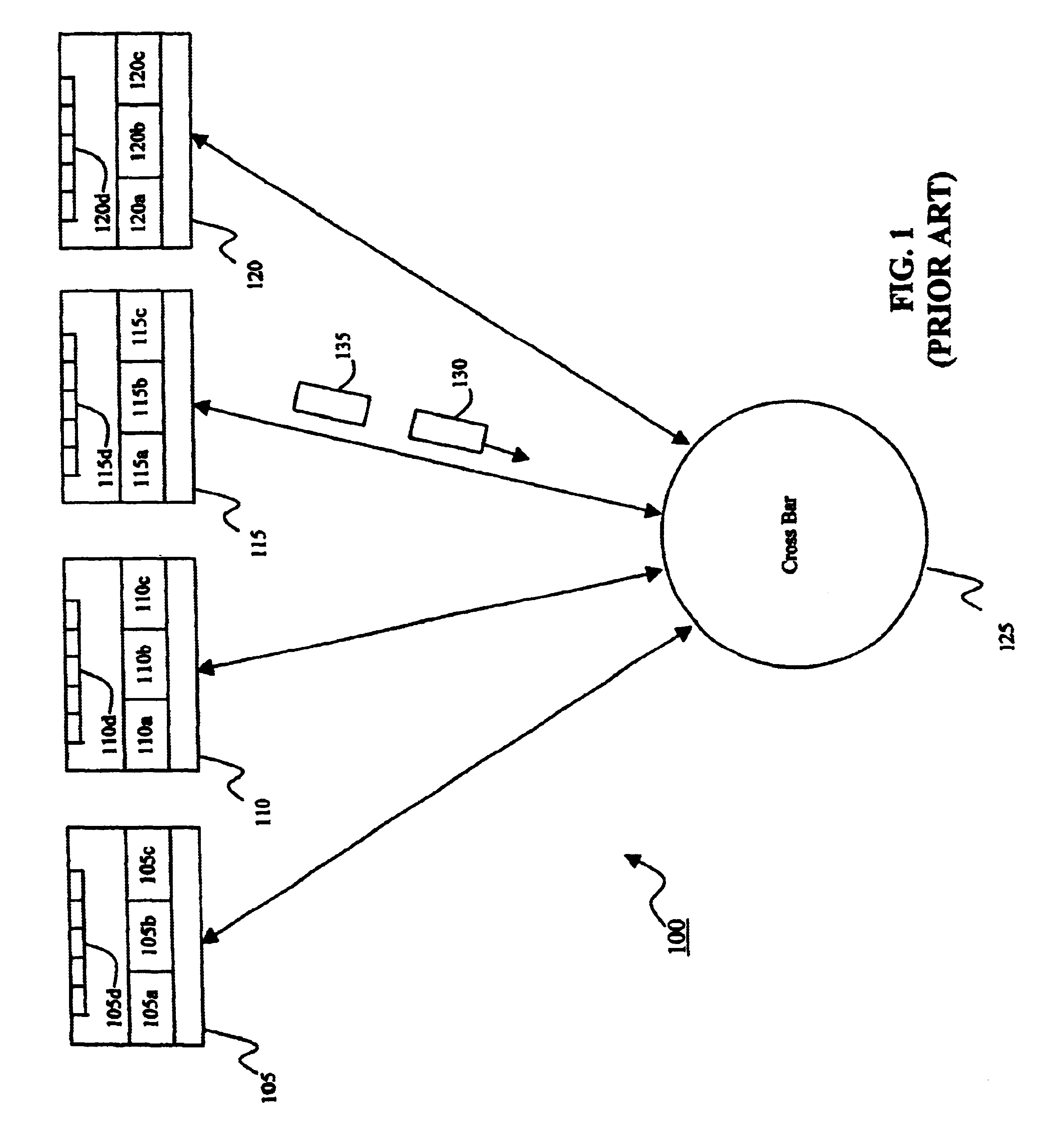
A packet destined for a busy port in another switch-node can thus block other packets destined for other non-busy ports, thereby resulting in a "head-of-line" blocking problem.
Thus, the head-of-line blocking problem can lead to undesirable performance such as packet transmission delay.
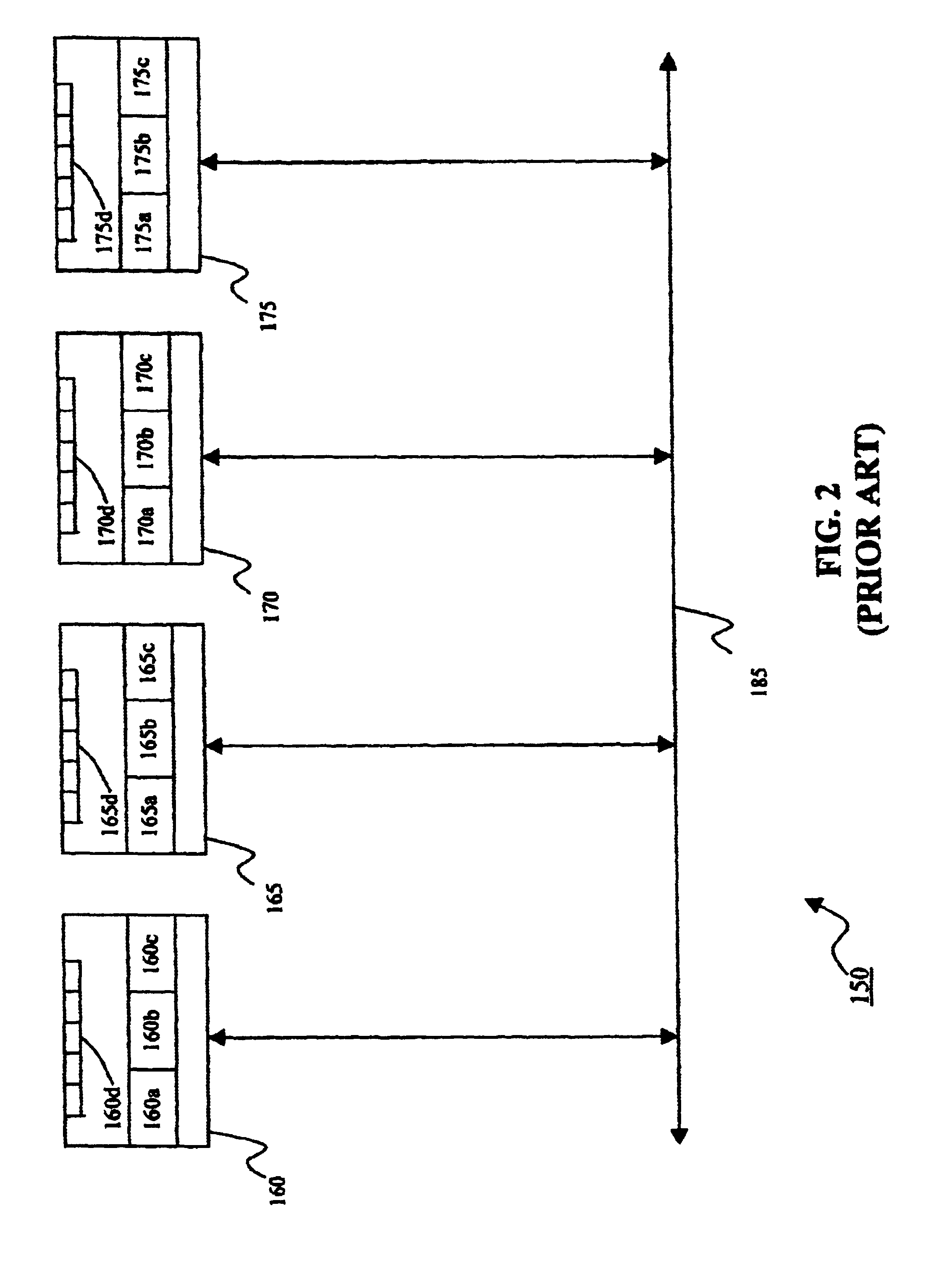
A disadvantage of the shared-bus design in FIG. 2 is as follows.
An increased load limits the frequency of operation of the network switch 150, thereby limiting switching capacity.
However, SRAM devices are expensive (as compared to dynamic random access memory (DRAM) devices).
In the conventional switch systems 100 and 150 (FIG. 1 and FIG. 2, respectively), SRAM devices of sufficient sizes can be implemented, but this option leads to higher cost.
Alternatively, the sizes of the SRAM devices can be made smaller to reduce cost, but decreasing the memory sizes will limit the bandwidth capacity of the switch system.
A limited bandwidth capacity leads to a limited switching capability.
Additionally, the conventional switch systems 100 and 150 require additional hardware to implement the switch-nodes in the network, thereby resulting in additional implementation costs.
However, chassis-based designs also increase the overall cost of switch systems.
In addition, chassis-based designs have poorer integration characteristics, since these designs require a given amount of logic to be implemented in multiple cards.
It should be noted that frames may have an arbitrary size that result in data not fully consuming a 64-byte packet.
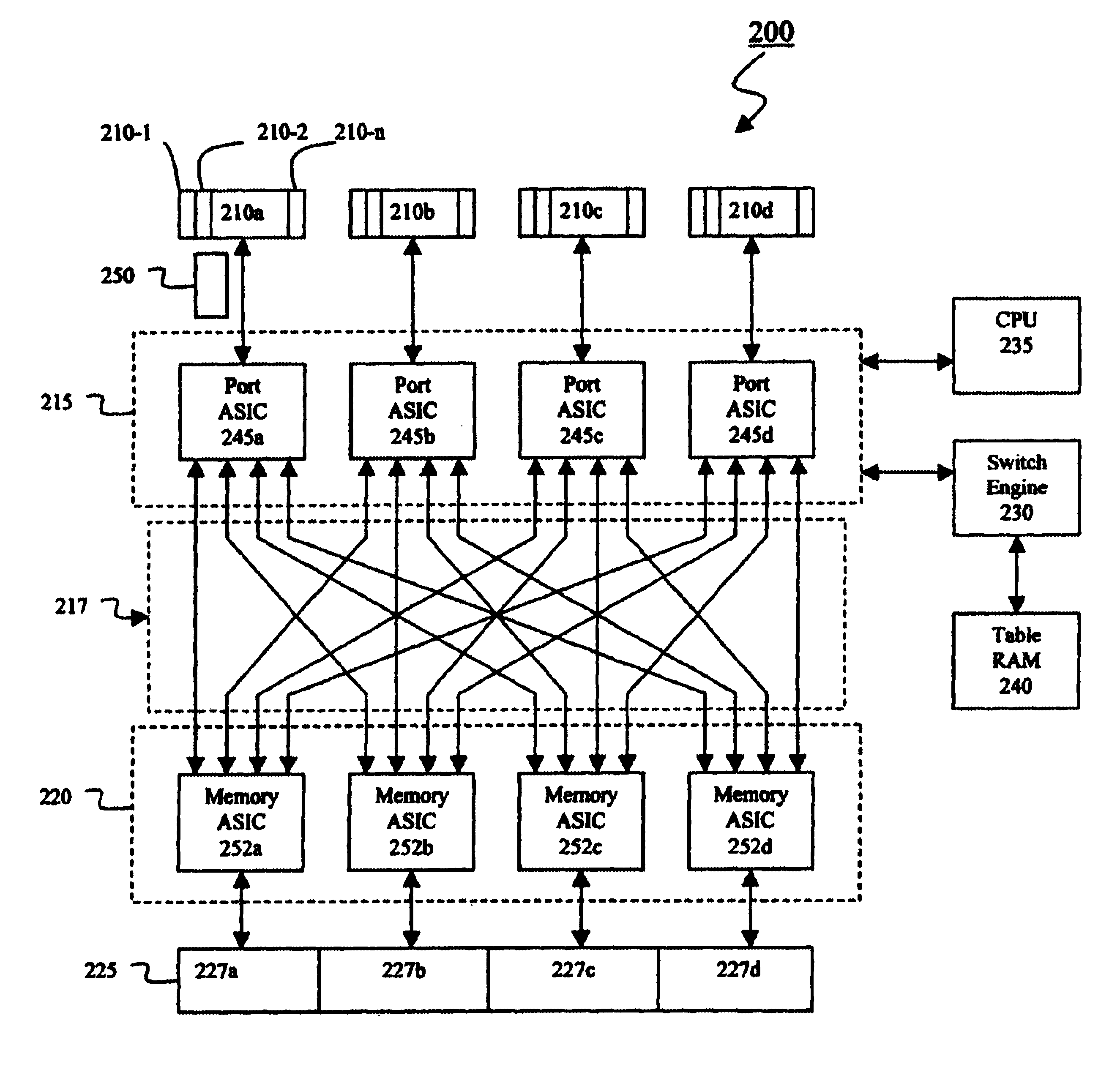
However, an N number of channels can be implemented for the Memory ASIC 252, with the number of channels being limited by die size, pin count, and other constraints based on whether the ASIC is to be implemented on a single integrated circuit chip or multiple integrated circuit chips.
Additionally, since SRAM devices are more expensive than DRAM devices, the use of SRAM devices can increase system cost by as much as about three to four times as compared to the present invention.

Method used


Image

  • Distributed switch memory architecture
  • Distributed switch memory architecture
  • Distributed switch memory architecture

Examples


example 2

ndwidth of 16 Gbits / s is achieved by configuring two 64-bit SDRAM ports at 125 MHz per Memory ASIC.

example 3

ndwidth of 19:2 Gbits / s is achieved by configuring four Rambus DRAM ports at 600 MHz per Memory ASIC.

As memory technology advances, the advances can be incorporated in the memory switch system of the invention by appropriately configuring the Memory ASICs 252a-252d and the memory pool 225 as discussed above. Other parts of the switch system 200 need not be affected. Additionally, as alluded to above, the ports 210-1 . . . 210-n can share the use of the memory pool 225, and the memory pool 225 is available to be shared unequally by all ports 210-1 . . . 210-n. Thus, each port 210-1 . . . 210-n is not subject to a "fixed-size" limitation. In contrast, under the more restrictive "fixed-size" design, ports of a given node can only share memory addresses which are available for that given node.

Moreover, it is possible to utilize the memory banks of DRAM devices so that, for example, a packet chunk is being received or stored in one memory bank of a given DRAM device, while another packet...


PUM


Abstract

A distributed memory switch system for transmitting packets from source ports to destination ports, comprising: a plurality of ports including a source port and a destination port wherein a packet is transmitted from the source port to the destination port; a memory pool; and an interconnection stage coupled between the plurality of ports and the memory pool such that the interconnection stage permits a packet to be transmitted from the source port to the destination port via the memory pool.

Description

1. Field of the InventionThis invention relates generally to the field of network switching and more specifically to a switch architecture capable of transmitting packets between ports in which a switch memory for temporarily storing packets while forwarding decisions are made is configured as a pool that is available to all ports in the switch.2. Description of the Related ArtNetwork switches provide a solution to client congestion problems by switching network traffic at high speeds between ports, rather than having every user broadcast to every other user in the network. Network switches enable information (formatted into packets) to be switched from one port to another port based upon the Ethernet addresses embedded in the packets. Conventional network switches are formed with switch-nodes that are interconnected to each other. Each switch-node typically has a physical link to an interconnection matrix which switches data between different switch-nodes. The interconnection matri...

Claims


Application Information

Patent Timeline
IPC IPC(8): H04L12/56
CPCH04L49/30H04L49/3072H04L49/90H04L49/9021H04L49/101H04L49/15H04L49/3036H04L49/351
Inventor AKELLA, VISVESWARSHARMA, SANJAYBOMMIREDDY, AMALKIRANVENKATACHALAM, DINESH
Owner INTEL CORP
Learn More