Magnetoelastic torque sensor

a technology of magnetoelastic torque and sensor, which is applied in the direction of distance measurement, instruments, surveying and navigation, etc., can solve the problems of increasing the cost and complexity of such a system, the inability of commercially competitive use of vehicle steering systems, and the relatively unstable and limited reliability of contact-type sensors. achieve the effect of increasing accuracy

Inactive Publication Date: 2004-03-02
METHODE ELETRONICS INC
View PDF30 Cites 75 Cited by
  • Summary
  • Abstract
  • Description
  • Claims
  • Application Information

AI Technical Summary

Benefits of technology

In view of the foregoing, it is an object of the present invention to provide a magnetoelastic torque sensor providing increased accuracy.
A second object of the present invention is to reduce the cost of manufacturing a magnetoelastic torque sensor.
Another object of the present invention is to reduce sensitivity of a magnetoelastic torque sensor to external, ambient magnetic fields.
A further object of the present invention is to reduce the strict homogeneous magnetic requirements of saturable magnetoelastic material used in magnetoelastic torque sensors.

Problems solved by technology

However, such contact-type sensors are relatively unstable and of limited reliability due to the direct contact with the rotating shaft.
In addition, they are very expensive and are thus commercially impractical for competitive use on vehicle steering systems.
It is recognized that the cost and complexity of such a system increases with the number of magnetic field sensors, whereas reliability is reduced.
In many of the prior art solutions, this necessitates the use of numerous discrete sensors, with corresponding additional cost.

Method used


Image

  • Magnetoelastic torque sensor
  • Magnetoelastic torque sensor
  • Magnetoelastic torque sensor

Examples


first embodiment

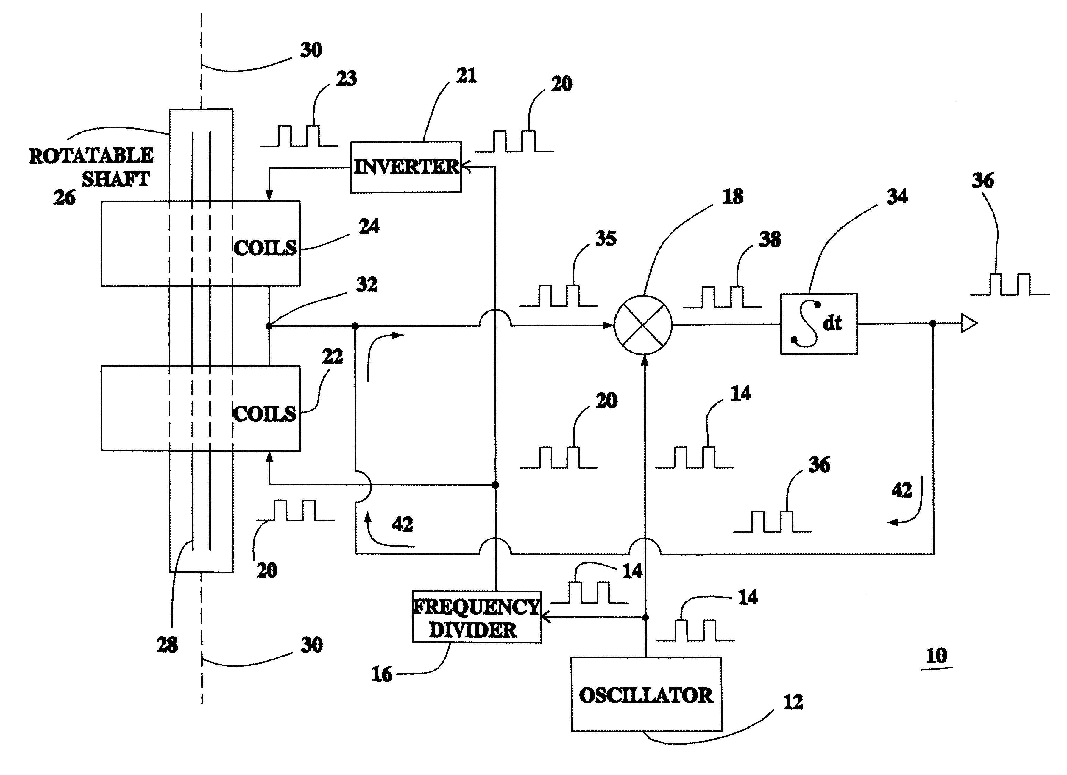
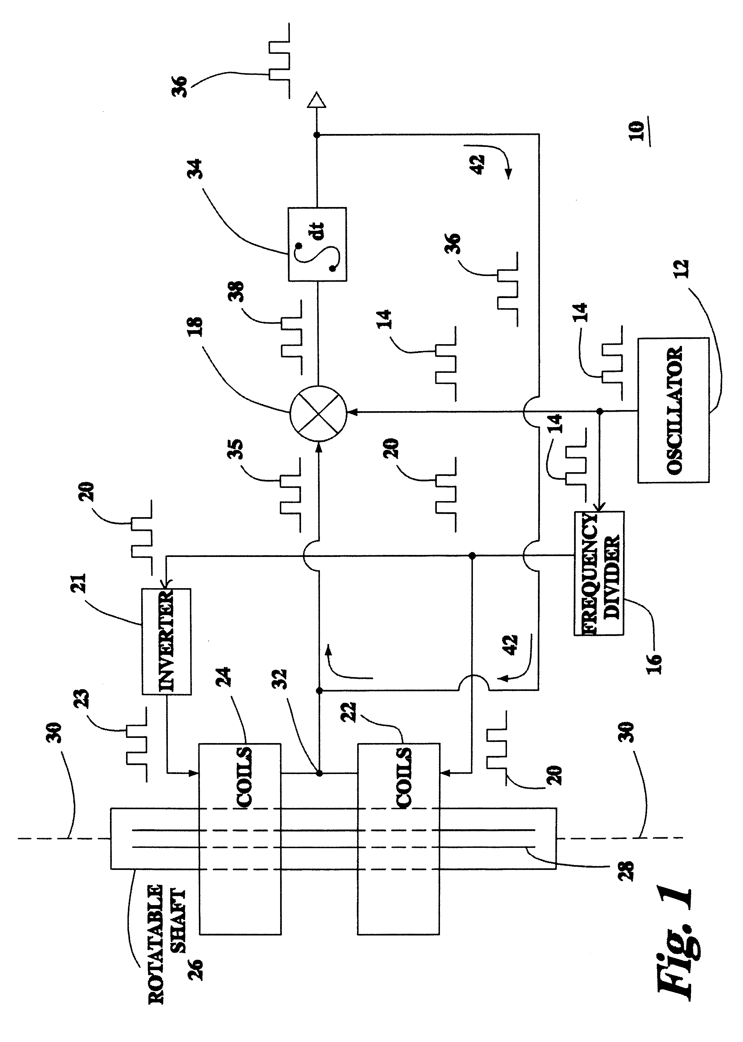
Referring now to the drawings, FIG. 1 shows a block diagram of a flux-gate magnetometer torque sensor 10 configured in accordance with a preferred first embodiment of the present invention. An oscillator 12 generates a square wave signal 14 that is received by a frequency divider 16 and a first input of a multiplier 18. The frequency of the square wave signal 14 is divided in two by the frequency divider 16. The divided square wave signal 20 is inputted into inductor coil 22 and signal inverter 21, which outputs inverted signal 23 into inductor coil 24. The inductor coils 22 and 24 encircle a rotatable shaft 26 at two separate locations.

In accordance with the present invention, a plurality of strips or wires 28 of magnetically saturable material is mounted to the rotatable shaft 26. Each strip 28 is mounted parallel to an axis of rotation 30 of the rotatable shaft 26. The strips or sense wires 28 are driven into a saturated state twice every cycle of the divided signal 20.

The output...

second embodiment

FIG. 3A illustrates the bobbin 70 shown in FIG. 3. In this embodiment the sense wires or wire strips are bonded to an internal diameter surface 71 of the bobbin 70. This embodiment may be preferred in applications where the shaft will be spinning at very high RPM's where the resulting centripetal forces would preclude mounting the sensor to the shaft surface. In this embodiment, there is no suppression of any rotational signal inherent to the shaft; instead, low-pass filtering of the output signal can be used to attenuate any rotational signal. The conductive sleeve 84 is mounted to the internal surface diameter 71 of the bobbin 70, sandwiching the sense wires 28 between the conductive sleeve 84 and the inner surface 71 of the bobbin 70.

FIG. 4 depicts a block diagram of the magnetic field sensor in conjunction with the magnetoelastic shaft 26. The magnetoelastic shaft 26 is shown at left, with the sense wires 28 shown as a non-linear transformer core. A coil 90 is shown coupled to t...


PUM

PropertyMeasurementUnit
diameteraaaaaaaaaa
magnetic fieldaaaaaaaaaa
magnetic anisotropyaaaaaaaaaa

Abstract

A flux-gate magnetometer torque sensor is provided having a rotatable shaft to which a torque force is to be applied, a sleeve of conductive foil affixed to the surface of the shaft over the magnetically active regions, a plurality of saturable magnetic wires or strips mounted to the rotatable shaft and parallel to an axis of rotation, sensor circuitry containing an oscillator for generating a signal, a divider coupled to the oscillator for dividing the frequency of the signal by two, a first and second coil each surrounding a different section of the rotatable shaft and having an input coupled to the divider output, a multiplier having inputs coupled to outputs of the first coil, the second coil, and the oscillator, and an integrator having an input coupled to the multiplier output and an output coupled to both outputs of the first and second coils, wherein the output voltage of the integrator corresponds to the torque being applied to the rotatable shaft.

Description

The present invention relates to magnetic sensors as applied to a magnetically active shaft structure, and more particularly, to non-contacting magnetoelastic torque transducers for measuring torque applied to a rotating shaft.Measurement of torque is generally a primary consideration in systems utilizing rotating drive shafts. Determining torque applied to a rotating shaft in an accurate, reliable and inexpensive manner is a primary goal. For example, determining torque is critical in power steering systems of modern automobiles. In such systems, an electric motor assists the vehicle's steering system in response to torque applied to the steering wheel by the driver. While advances have been made in power steering systems, there remains a compelling need for inexpensive torque sensing devices that are capable of continuous torque measurement over extended periods of time despite severe environmental and operating conditions.Prior art torque measurement has been accomplished by usin...

Claims


Application Information

Patent Timeline
Patent Type & Authority Patents(United States)
IPC IPC(8): G01L3/10B62D1/16
CPCG01L3/102G01L3/105
Inventor CRIPE, DAVID W.
Owner METHODE ELETRONICS INC
Why Eureka
Try Eureka