Liquid crystal display unit having fine color control

a liquid crystal display and color control technology, applied in the field of liquid crystal display units, can solve the problems of rgb crosstalk, inconvenient gray scale display, interference with color display performance, etc., and achieve the effect of reducing the sensing of gray scale coloring and high precision

Inactive Publication Date: 2004-03-02
SHARP KK
View PDF10 Cites 104 Cited by
  • Summary
  • Abstract
  • Description
  • Claims
  • Application Information

AI Technical Summary

Benefits of technology

In order to solve the above problems, the present invention has been provided. It is an object of the invention to provide a liquid crystal display unit that can correct color reproduction particular to a liquid crysta

Problems solved by technology

This not only causes an inconvenience in the gray scale display, but also interferes with color display performance.
Particularly, there is a problem that when a gray portion such as a shade exists in the image, a color appears in this portion.
Further, in the color image display according to this color filtering method, a light from the pixel does not enter the corresponding RGB filter in an ideal manner, and the light leaks to another filter, which causes RGB crosstalk.
This RGB crosstalk disturbs the color balance, and makes it impossible to reproduce a desired color.
However, this method also has many problems because the cost, the weight and the thickness are doubled and the manufacturing process is complex.
However, it is impossible to completely match the phase-difference wavelength dispersion characteristics of the liquid crystal panel with the phase-difference wavelength dispersion characteristics of the polymer film.
Therefore, it is not possible to compensate for the phase difference over the whole visible area.
However, this method has a problem of being costly and the contrast is lowered.
However, it is difficult to prepare a film that matches with the optical rotary dispersion characteri

Method used


Image

  • Liquid crystal display unit having fine color control
  • Liquid crystal display unit having fine color control
  • Liquid crystal display unit having fine color control

Examples


first embodiment

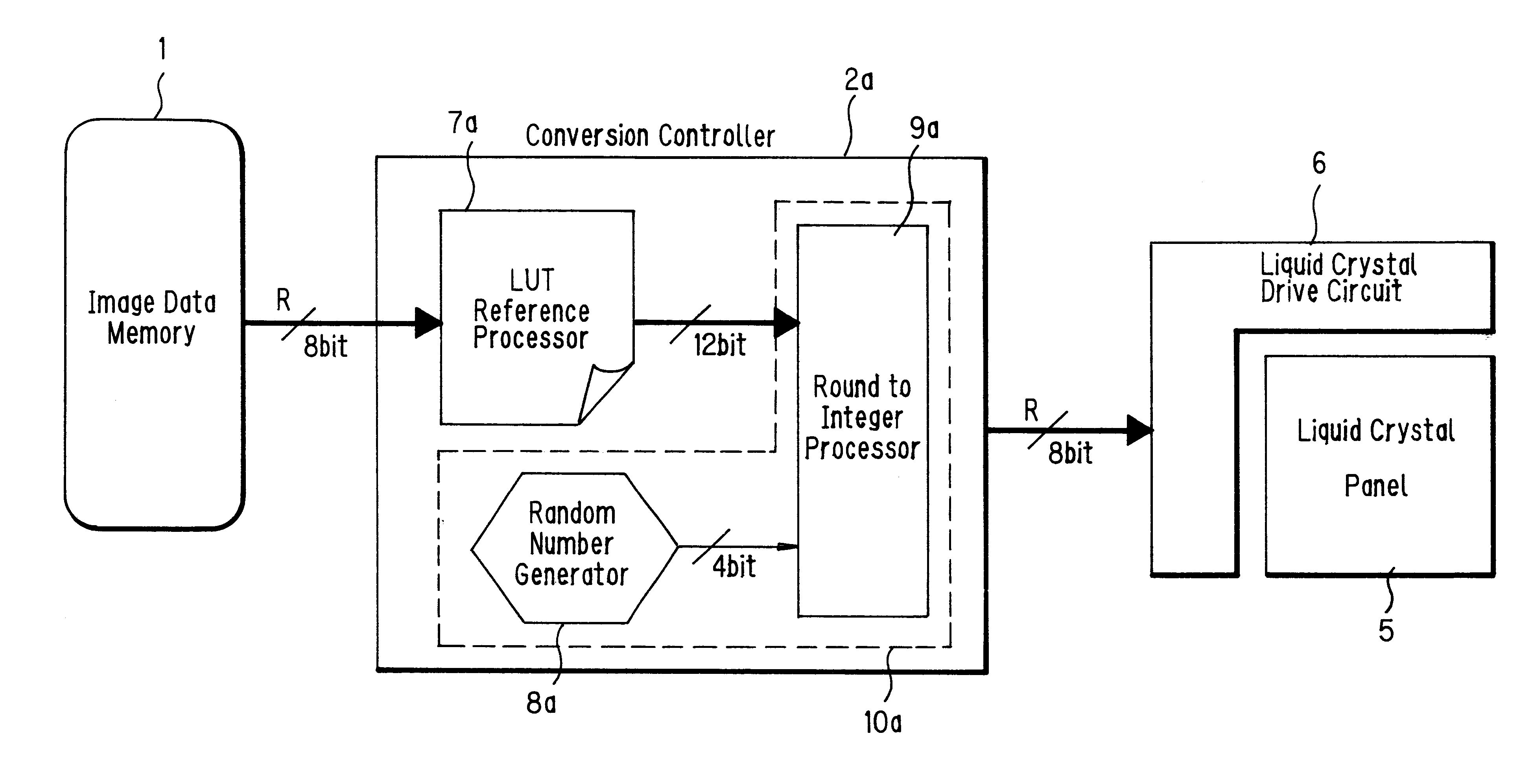
FIG. 5 is a block diagram showing a first embodiment of a liquid crystal display unit relating to the present invention. As shown in FIG. 5, a reference number 1 denotes an image data memory that stores RGB digital image data, 2a, 2b and 2c denote conversion controllers that control conversion of image data of R, G and B respectively, 5 denotes a liquid crystal panel that can output RGB colors, and 6 denotes a digital interface liquid crystal drive circuit that displays supplied digital image data in the liquid crystal panel 5. Eight-bit digital image data of R, G and B respectively that have been output from the image data memory 1 are corrected by the conversion controllers 2a, 2b and 2c to match the liquid crystal panel characteristics. The corrected data are input to the liquid crystal drive circuit 6 as eight-bit digital image data, and are displayed by the liquid crystal panel 5.

FIG. 6 is a block diagram showing the conversion controller 2a of the R image data. As shown in FIG...

second embodiment

FIG. 8 is a block diagram showing a second embodiment of a liquid crystal display unit relating to the present invention. Portions that are the same as those of the first embodiment are labeled with identical reference numbers and their explanation will be omitted. As shown in FIG. 8, a reference number 13 denotes a horizontal pixel counter. This horizontal pixel counter 13 is for counting the pixel clock in a horizontal direction in four values at the timing when the image data memory 1 outputs the image data, and for supplying the counted pixel clock to the conversion processors 12a, 12b and 12c as two-bit horizontal count data. A reference number 14 denotes a vertical pixel counter. This vertical pixel counter 14 is for counting the pixel clock in a vertical direction in four values at the timing when the image data memory 1 outputs the image data, and for supplying the counted pixel clock to the conversion processors 12a, 12b and 12c as two-bit vertical count data.

FIG. 9 is a bl...

third embodiment

FIG. 12 is a block diagram showing a third embodiment of a liquid crystal display unit relating to the present invention. Portions that are the same as those of the first and second embodiments are labeled with identical reference numbers and their explanation will be omitted. As shown in FIG. 12, reference number 20 denotes a conversion controller. This conversion controller 20 consists of a matrix calculation processor 21 as correcting means, random number generators 8a, 8b and 8c, and round-to-integer processors 9a, 9b and 9c. Color improving means 22a, 22b and 22c consist of the random number generators 8a, 8b and 8c and the round-to-integer processors 9a, 9b and 9c, respectively. The matrix calculation processor 21 stores three-times-three matrix coefficients for carrying out a linear conversion of RGB image digital data according to the characteristics of a liquid crystal panel 5 shown in FIG. 12. These matrix coefficients are obtained by, for example, the method of least squa...


PUM


Abstract

Eight-bit digital image data of R, G and B output from an image data memory are corrected by conversion controllers to meet characteristics of a liquid crystal panel. The corrected data are input to a liquid crystal drive circuit as digital image data, and an image is displayed on the liquid crystal panel. A LUT stored in a LUT reference processor stores data (addresses) by a number that makes it possible to refer to input image digital data at one to one. A random number generator is for generating random numbers and supplying the random numbers to a round-to-integer processor as threshold value data. The round-to-integer processor compares the data referred to by the LUT reference processor with the threshold data, and carries out a round-to-integer processing.

Description

1. Field of the InventionThe present invention relates to a liquid crystal display unit that is used as a monitor for a personal computer (hereinafter to be referred to as a PC), a word processor, etc., and further as a display for a television receiver, and a projector. More specifically, the present invention relates to a liquid crystal display unit that carries out a control for matching an image to be displayed with the characteristics of a liquid crystal panel in order to obtain an image of a satisfactory color balance.2. Description of the Prior ArtIn recent years, along with the development of a liquid crystal panel having higher resolution and fuller color range, there has been an increase in demand for liquid crystal display units that have features such as low voltage driven, thin and light weight, in the information equipment field including personal computers as main products, and in the image equipment field including television receivers and projectors as main products...

Claims


Application Information

Patent Timeline
IPC IPC(8): G09G5/395G09G5/36G09G3/36G09G3/20G02F1/133G09G5/00H04N9/30
CPCG09G3/3611G09G5/006G09G5/395G09G2320/02
Inventor TANAKA, SEIICHISHIMIZU, HAJIMENAKAJIMA, TAKAYUKI
Owner SHARP KK
Why Eureka
Try Eureka