
Calibration of in-phase and quadrature transmit branches of a transmitter

a quadrature transmitter and transmitter technology, applied in the direction of line-transmission details, transmission monitoring, baseband system details, etc., can solve the problems of mismatch and customer requirements cannot be fulfilled, and achieve the effect of avoiding otherwise unnecessary repeatable calibration cycles and quick removal of large errors

Inactive Publication Date: 2004-03-09
KONINK PHILIPS ELECTRONICS NV
View PDF7 Cites 52 Cited by
  • Summary
  • Abstract
  • Description
  • Claims
  • Application Information

AI Technical Summary

Benefits of technology

to provide an effective and optimal method of calibrating a quadrature transmitter.
The invention is based on the insight to first and quickly remove large errors, such as a major part of DC-offset errors, in in-phase and quadrature transmit branches, thereby avoiding otherwise unnecessary repetitious calibration cycles.

Problems solved by technology

Due to asymmetrical layout of diverse components of the transmitter on the chip, such as off-center positioning of transmit filters or other components, mismatch occurs.
Such unwanted LO components, also known as LO-feedthrough, might be of such a severe nature, depending on component and IC-process spread, that customer requirements can no longer be fulfilled.

Method used


Image

  • Calibration of in-phase and quadrature transmit branches of a transmitter
  • Calibration of in-phase and quadrature transmit branches of a transmitter
  • Calibration of in-phase and quadrature transmit branches of a transmitter

Examples


Embodiment Construction

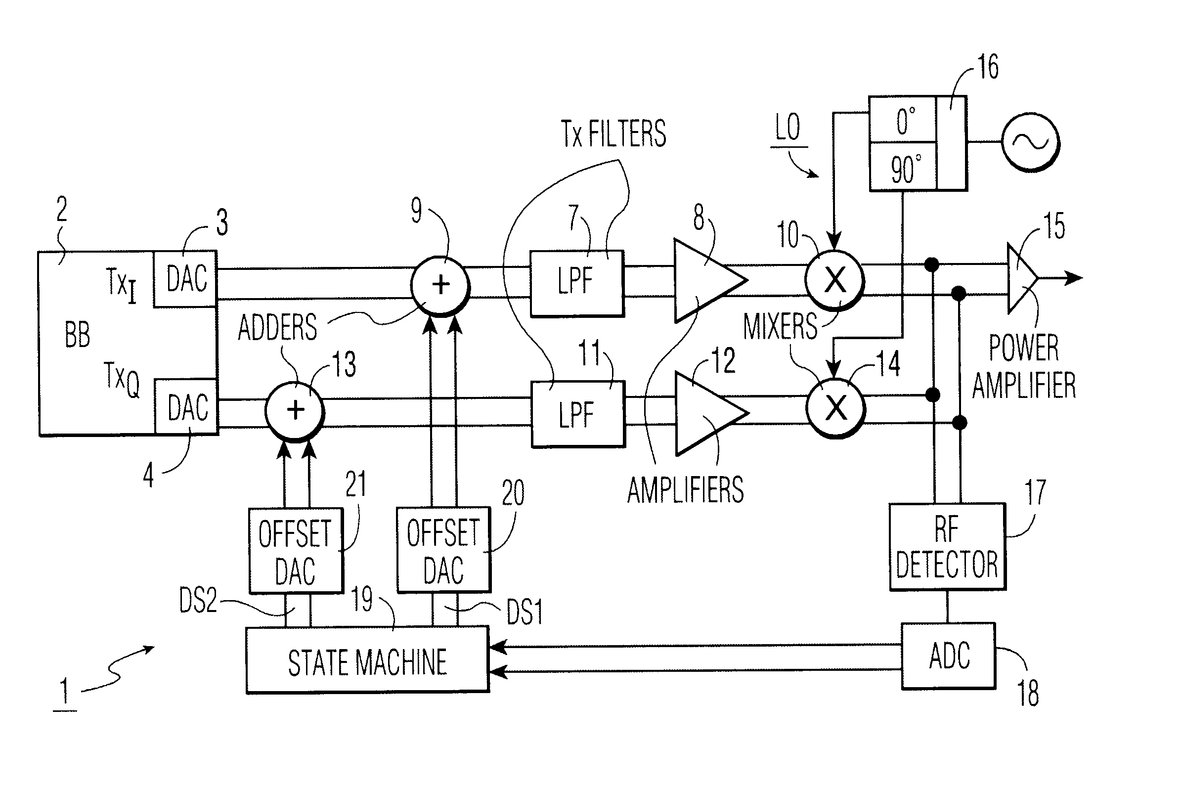
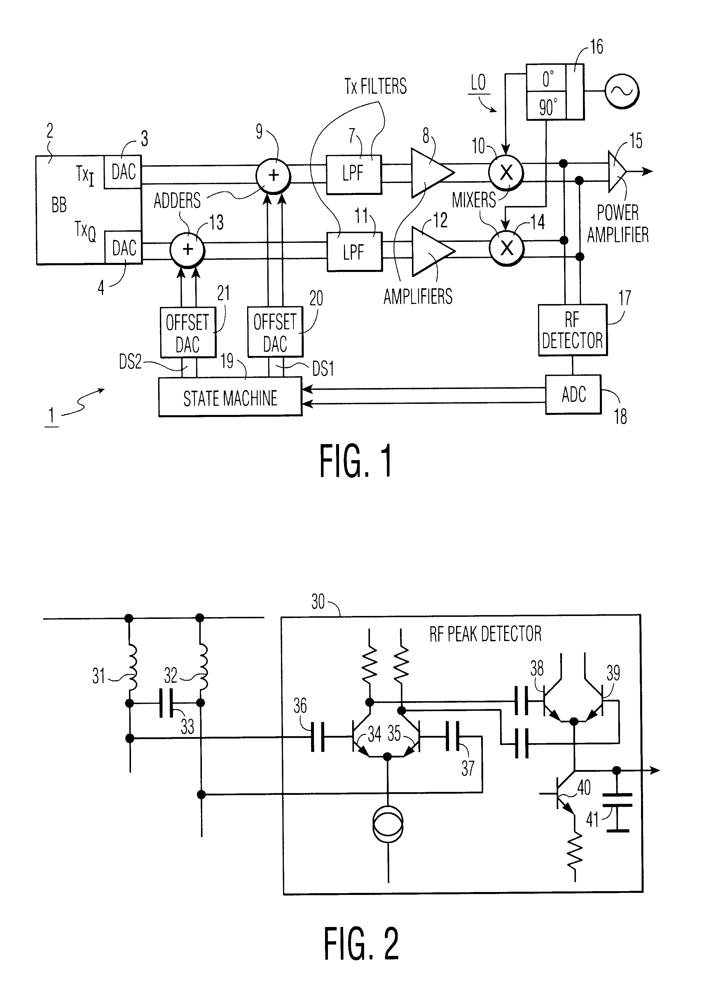
FIG. 1 is block diagram of a quadrature transmitter 1 according to the invention. The transmitter 1 comprises a base band circuit or chip 2 that, through digital-to-analog converters (DAC) 3 and 4 respective base band transmit signals Tx.sub.I and Tx.sub.Q to an in-phase transmit branch 5 and a quadrature transmit branch 6. The in-phase transmit branch 5 comprises a low pass transmit filter 7, and amplifier 8, an injector or adder 9 and a mixer 10. The quadrature transmit branch 6 comprises a low pass transmit filter 11, an amplifier 12, an injector or adder 13 and a mixer 14. Output signals of the mixers 10 and 14 are combined and provided to a transmit power amplifier 15. A local oscillator circuit or synthesizer 16, including a 90.degree. phase shifter for the quadrature transmit branch 6, provides local oscillator signals to up-convert the base band transmit signal. In case of a zero-IF transmitter architecture, transmitter calibration is performed with the transmit base band si...


PUM


Abstract

In a method of calibrating a quadrature transmitter, a first calibration signal is injected into an in-phase transmit branch of the quadrature transmitter, and a second calibration signal is injected into a quadrature transmit branch of the quadrature transmitter. The first and second calibration signals are injected before performing up-conversion in the transmitter and are produced by first and second digital signals. A detector detects an up-converted signal. The detected up-converted signal is digitized. The in-phase and quadrature transmit branches are calibrated by alternately determining the first and second calibration signals while at least varying respective most significant bits of the first and second digital signals, upon said varying the at least most significant bits keeping calibration bit values that correspond to minimum values of the digitized detected up-converted signal.

Description

1. Field of the InventionThe present invention relates to calibration of in-phase and quadrature branches of a quadrature transmitter or transceiver, such transmitter or transceivers being based on a zero-IF or low-IF architecture. Such transmitters or transceivers can devices under the s-called IEEE 802.11a or IEEE 802.11b Standard, can be cell phones, or can be any other suitable radio frequency device.2. Description of the Related ArtTransmitters or transceivers based on a zero-IF (Intermediate Frequency) or low-IF architecture are well-known in the art. Such transmitters have an in-phase and quadrature transmit branch and an up-converter to up-convert a base band signal to a radio frequency signal, typically by a pair of quadrature mixers. Such zero-IF or low-IF transmitters are usually implemented as an integrated circuit on a chip. Due to asymmetrical layout of diverse components of the transmitter on the chip, such as off-center positioning of transmit filters or other compon...

Claims


Application Information

Patent Timeline
Patent Type & Authority Patents(United States)
IPC IPC(8): H03C3/00H03D7/16H03D7/00H03F3/45H03C3/40H03F1/30H04L27/00H04B1/04
CPCH03C3/406H03D7/168H03F1/304H03F3/45973H04L27/0014H04L2027/0016H04L2027/0018H04B1/04
Inventor RIOU, EMMANUELHAHN, WILLHELM STEFFENSCHUUR, AXEL ERICH
Owner KONINK PHILIPS ELECTRONICS NV
Learn More