Scleral plug system

a plug system and scleral plug technology, applied in the field of scleral plugs, can solve the problems of retinal detachment repair failure, difficult placement of plugs in sclerotomy, and fluid escape uncontrollable through the system,

Inactive Publication Date: 2004-03-16
CAMP MATTHEW W
View PDF3 Cites 68 Cited by
  • Summary
  • Abstract
  • Description
  • Claims
  • Application Information

AI Technical Summary

Benefits of technology

It is a further object of this invention to provide a cannulated plug that avoids expulsion of the retina.
It is another object of this invention to provide forceps with shortened tips for ease in handling scleral plugs.

Problems solved by technology

Proliferative vitreoretinopathy (PVR) is the leading cause of failure of retinal detachment repair.
The length of the tip, combined with the size of the tiny plug, makes it difficult to place a plug in a sclerotomy.
When using the plugs of the prior art, any breach in the system allows fluid to escape uncontrolled, e.g. a leak or an unplugged sclerotomy.
The release of RPE cells are believed to cause PVR, which results in loss of vision.
Fluid turbulence may cause even healthy retina to be drawn toward a sclerotomy and damaged.

Method used


Image

  • Scleral plug system
  • Scleral plug system

Examples


Embodiment Construction

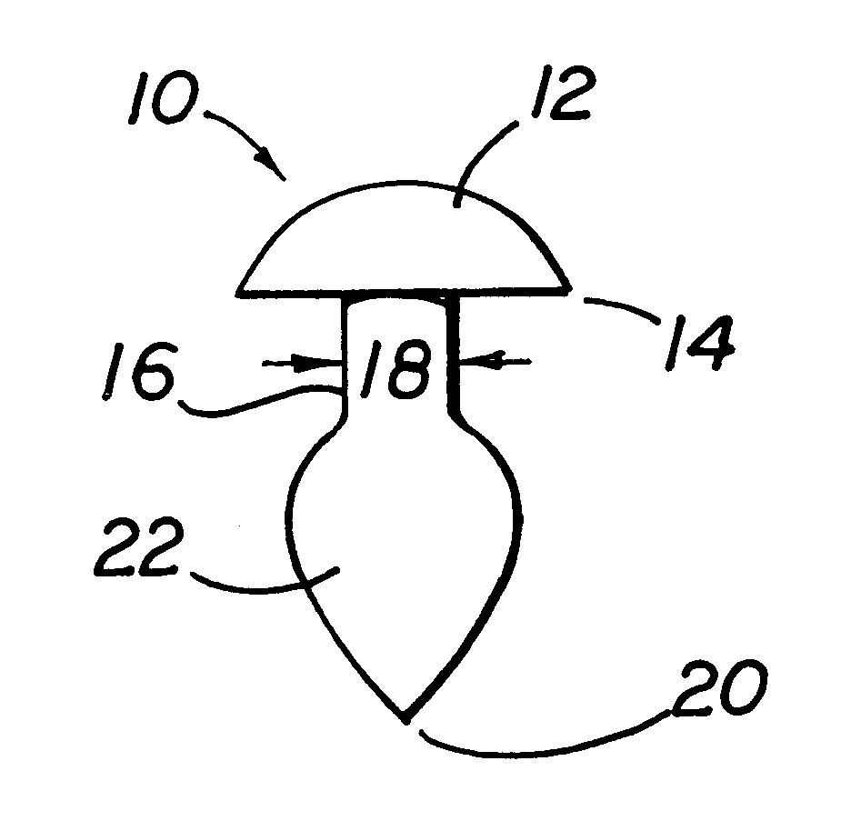
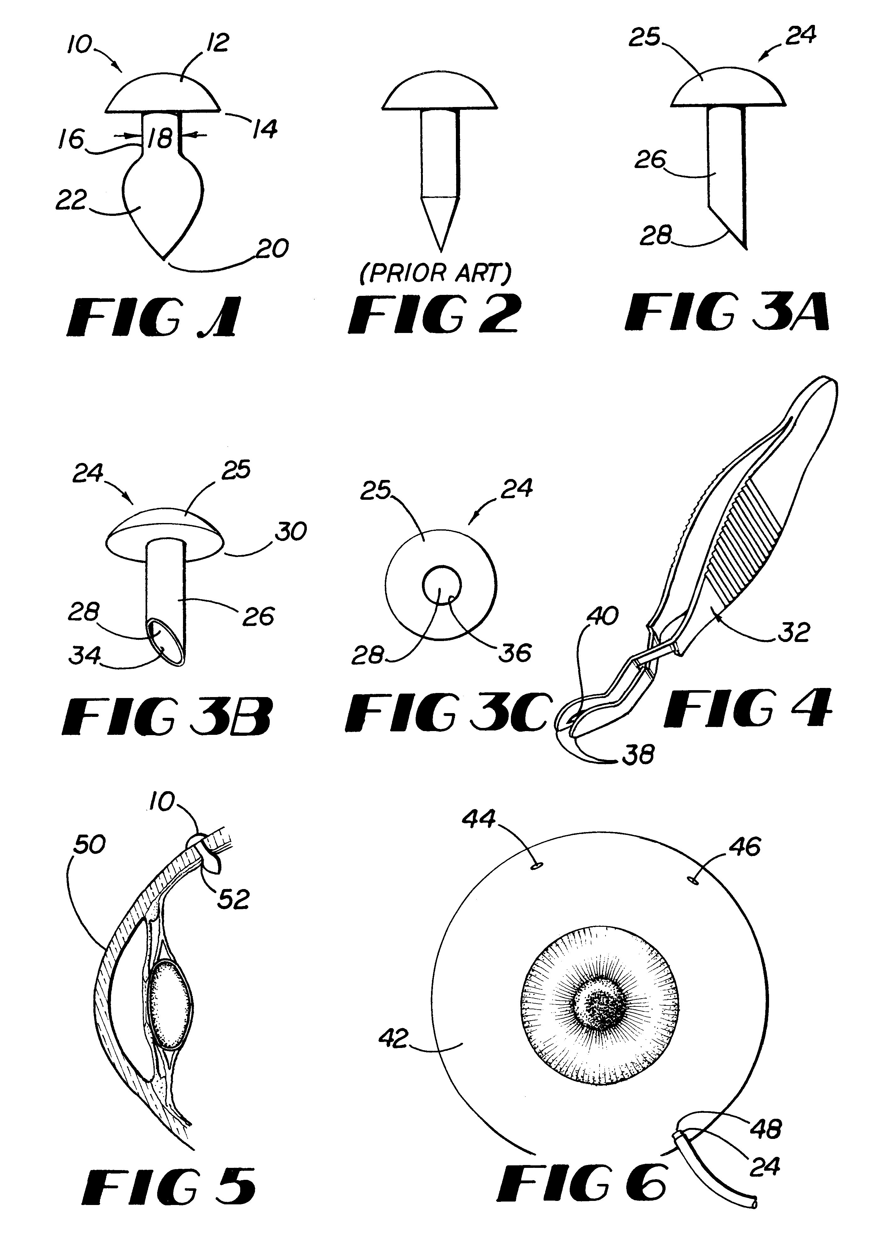
As shown in FIG. 1, scleral plug 10 has cap 12 at proximal end 14. Shaft 16 is attached to cap 12 at proximal end 14. Proximal end 14 of shaft 16 has diameter 18 that is equivalent to the diameter of the sclerotomy. Distal end 20 has bulbous portion 22. When placed in an eye during surgery, distal end 20 is first placed into the sclerotomy, or opening in the sclera. Bulbous portion 22 passes through the sclera to the interior portion of the eye. Reduced diameter proximal end 14 forms a watertight seal with the sclera. Reduced diameter proximal end 14 has a diameter so that it does not stretch the sclerotomy and is of a length to accommodate the thickness of the sclera. Cap 12 prevents plug 10 from slipping into the eye, while bulbous end 22 prevents plug 10 from slipping out of the eye and thereby disrupting the desired closed system.

As shown in FIGS. 3A-3C, cannulated scleral plug 24 has cap 25, shaft 26 and lumen 28. Cap 25 is attached at proximal end 30. Lumen 28 has distal openi...


PUM


Abstract

Scleral plug system for occluding a hole in the eye and for controlling irrigation during vitreo-retinal surgery in order to maintain a closed system during the procedure, and angled forceps for handling a scleral plug.

Description

1. Field of the InventionThis invention relates to a scleral plug for occluding a hole in the eye and for controlled irrigation during vitreo-retinal surgery in order to maintain a closed system during the procedure, and angled forceps for handling the plugs.2. Description of Related ArtModern vitreo-retinal surgery allows ophthalmologists to diagnose and treat diseases of and injuries to the posterior segment of the eye. Vitreo-retinal surgery involves the use of small needle instruments to remove, for example, the vitreous humor, hemorrhage, scar tissue, infection or foreign bodies.A typical three port vitrectomy utilizes an infusion cannula, which maintains a preset tension in the eye, and multiple hand-held instruments for illumination, cutting, grasping, and suction. A carefully constructed environment must be maintained within the eye at all times for these procedures to be successful. The surgeon uses microsurgical techniques to manipulate the delicate tissue within the eye. ...

Claims


Application Information

Patent Timeline
Patent Type & Authority Patents(United States)
IPC IPC(8): A61F9/007A61B17/00A61B17/30A61B17/064
CPCA61B17/0057A61F9/00772A61F9/00781A61B17/064A61B17/30A61B2017/00659A61B2017/0647
Inventor CAMP, MATTHEW W.
Owner CAMP MATTHEW W
Why Eureka
Try Eureka