Three state transflective liquid crystal display

Inactive Publication Date: 2004-03-16
138 EAST LCD ADVANCEMENTS LTD
View PDF22 Cites 69 Cited by
  • Summary
  • Abstract
  • Description
  • Claims
  • Application Information

AI Technical Summary

Problems solved by technology

Although a reflective liquid crystal device is generally used for the display unit of a portable electronic apparatus, it has a problem in that a display cannot be recognized in the dark because of the use of external light incident on a liquid crystal layer from the front side of a liquid crystal cell.
However, the transflective liquid crystal device disclosed in the above publication comprises a transparent substrate interposed between the liquid crystal layer and the transflector, and thus causes a double image due to parallax when reflective display is performed.
Particularly, a

Method used


Image

  • Three state transflective liquid crystal display
  • Three state transflective liquid crystal display
  • Three state transflective liquid crystal display

Examples


first embodiment

The following description assumes therefor the light emitted from the illumination device and passing through the transflector is changed to left-handed circularly polarized light, not right-handed circularly polarized light in the

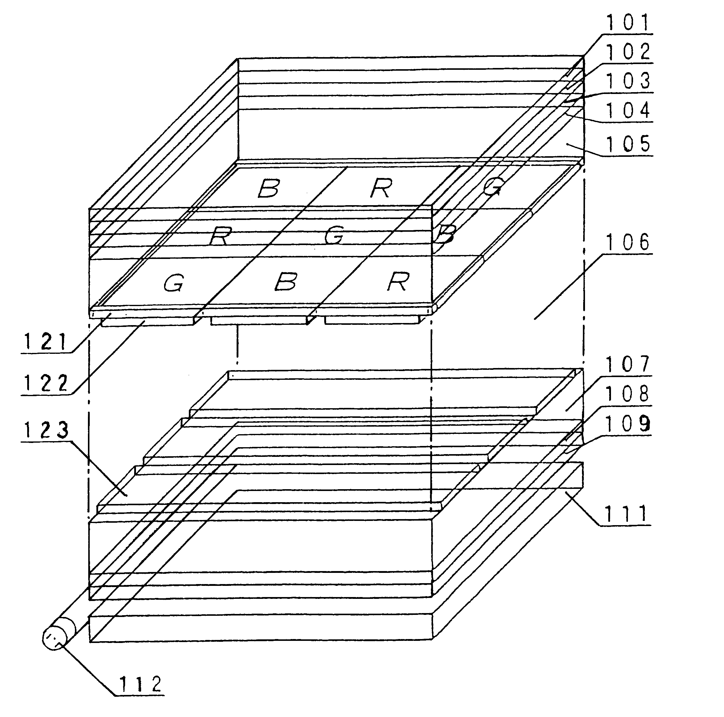
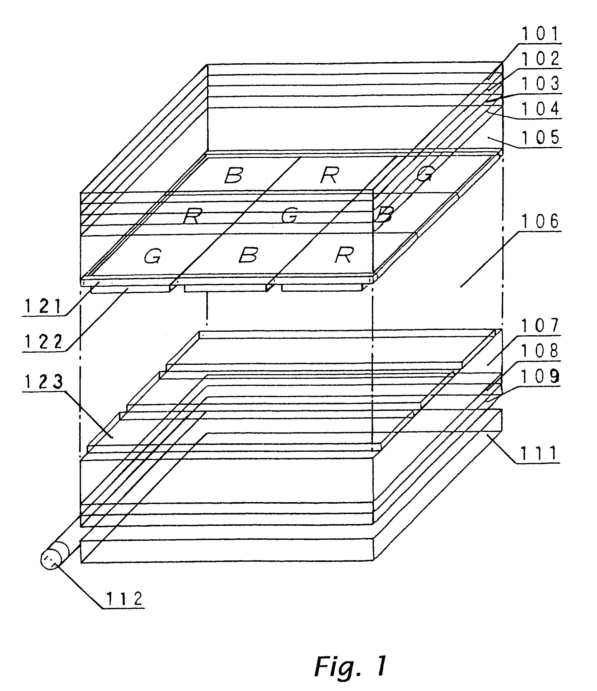
Only the panel conditions were changed to those shown in FIG. 5 with the structure of the liquid crystal device shown in FIGS. 1 and 2 unchanged. In FIG. 5, five laminated rectangles represent a first polarizer, first and second retardation plates, a liquid crystal cell, a third retardation plate, and a second polarizer, respectively, in turn from the top, and an arrow given in each of the rectangles indicates the axial direction.

The absorption axis direction 501 of the first polarizer is at left 35.5.degree. with respect to the direction of the panel length. The retardation axis direction 502 of the first retardation plate is at left 102.5.degree. with respect to the direction of the panel length, with a retardation of 455 nm. The retardation axis directi...

third embodiment

The third embodiment concerns an another example of the illumination device which can be applied to the transflective liquid crystal devices of the first and second embodiments. The third embodiment uses a blue EL having a light emission peak at a wavelength of 480 nm in place of the illumination device denoted by 111 and 112 in FIG. 1, or the illumination device denoted by 711 and 712 in FIG. 7. Therefore, a film having a retardation of 120 nm is used as a second retardation plate so that the light emitted from the illumination device is blue light at a wavelength of 480 nm and changed to elliptically polarized light with high ellipticity.

In the above-described structure of this embodiment, it is possible to provide a transflective liquid crystal device capable of performing transmissive display with high contrast even when a color illumination device emitting colored light is used.

fourth embodiment

The fourth embodiment concerns an example of a reflective polarizer which can be applied to the transflective liquid crystal devices of the first to third embodiments. The fourth embodiment is different from the above embodiments in that a reflective polarizer is used in place of the second polarizer 109 shown in FIG. 1 or the second polarizer 709 shown in FIG. 7.

As the reflective polarizer, a birefringent dielectric multilayered film is used. The birefringent dielectric multilayered film has the function to reflect a predetermined linearly polarized light component and transmit other polarized light components. Details of the birefringent dielectric multilayered film are disclosed in the international application (International Application No.: WO97 / 1788) and Japanese Unexamined Patent Publication No. 9-506985. Such a reflective polarizer is commercially available as DBEF (trade name) from U.S. 3M Co., Ltd.

The axial direction of the reflective polarizer is arranged so that the refl...


PUM


Abstract

A liquid crystal device of the present invention performs transmissive display using light from an illumination devices 111 and 112 in a dark environment, and reflective display using light reflected by a transflective layer 123 provided on the inner side of a liquid crystal cell in a bright environment. A retardation plate is provided adjacent to a polarizer 109 and an illumination device so that the rotational direction of polarization of the light emitted from the illumination device is the same as that of the polarization of the light reflected by the transflective layer in a dark display state.

Description

1. Technical FieldThe present invention relates to a liquid crystal device, and particularly to a transflective liquid crystal device having both the reflective display function of performing display by reflecting light, which is incident on a liquid crystal layer from a front side of liquid crystal cell, by a transflective layer, and the transmissive display function of performing display by transmitting light, which is incident on the liquid crystal layer from a back side, through the transflective layer. The present invention also relates to an electronic apparatus using the liquid crystal device.2. Background ArtAlthough a reflective liquid crystal device is generally used for the display unit of a portable electronic apparatus, it has a problem in that a display cannot be recognized in the dark because of the use of external light incident on a liquid crystal layer from the front side of a liquid crystal cell. Therefore, a transflective liquid crystal device has been proposed i...

Claims


Application Information

Patent Timeline
IPC IPC(8): G02F1/13G02F1/1335G02F1/1343G02F1/13357G02F1/13363
CPCG02F1/133555G02F1/13363G02F1/134336G02F2001/133626G02F2001/133638G02F2202/40G02F2413/04G02F2413/08G02F1/133626G02F1/133638G02F2201/34
Inventor OKUMURA, OSAMUMAEDA, TSUYOSHIOKAMOTO, EIJISEKI, TAKUMI
Owner 138 EAST LCD ADVANCEMENTS LTD
Why Eureka
Try Eureka