Top and bottom ultraviolet sterilization system

a sterilization system and ultraviolet radiation technology, applied in the field of improvement, can solve the problems of lingering bacteria on the surface, unable to completely sanitize the article by ultraviolet radiation using the conventional conveyor system, and casting radiation "shadows" on certain parts of the underside of the article being treated

Inactive Publication Date: 2004-03-23
UV DOCTOR
View PDF1 Cites 41 Cited by
  • Summary
  • Abstract
  • Description
  • Claims
  • Application Information

AI Technical Summary

Problems solved by technology

However, even though both of these conventional systems allow significant portions of the underside of articles transported through the irradiation tunnel to be exposed to ultraviolet radiation, the structures of conventional conveyor systems of this type do cast radiation "shadows" on certain portions of the undersides of the articles being treated.
As a consequence, these articles cannot be completely sanitizing by ultraviolet radiation using conventional conveyor systems.
A further difficulty in sanitizing articles conveyed past an ultraviolet irradiation source is that the presence of surfaces parallel to the rays of the irradiation source and also indentations and other nooks and crannies in the articles prevents the ultraviolet radiation from striking all of the surfaces of the articles.
Consequently, bacteria can linger untreated in areas on the surfaces of the articles that do not receive direct or reflected ultraviolet radiation.
Still another problem that exists in conventional ultraviolet irradiation tunnels is that the lamps emitting the ultraviolet radiation tend to deteriorate rather rapidly, particularly if they are constructed as elongated tubes.
The problem that arises is that conventional ultraviolet radiation lamp tubes are supported at their ends, but are unsupported between their ends.
Any support between the ends of the tubes would interfere with the radiation emitted.
As a consequence, with the intense heat that is built up in the generation of ultraviolet radiation, the tubular structure of the ultraviolet radiation lamps softens and tends to sag at the centers of the lamps.
Also, this deformation of the bodies of the tubes causes structural damage, leading to premature failure of the ultraviolet radiation lamps.
The longer the tubes, the greater the likelihood of damage in this connection.
This maintenance procedure does prolong the life of the lamp, but requires the combined effort of two persons to rotate each lamp.
This is often difficult or inconvenient, since one side of the tunnel may be located close to a wall of a room in which the tunnel is located.
This maintenance process is therefore rather time-consuming and requires two people.
Also, the sides of the lamps facing the reflectors are subject to a much higher level of heat than the sides of the lamps facing the articles passing therebeneath.

Method used


Image

  • Top and bottom ultraviolet sterilization system
  • Top and bottom ultraviolet sterilization system
  • Top and bottom ultraviolet sterilization system

Examples


Embodiment Construction

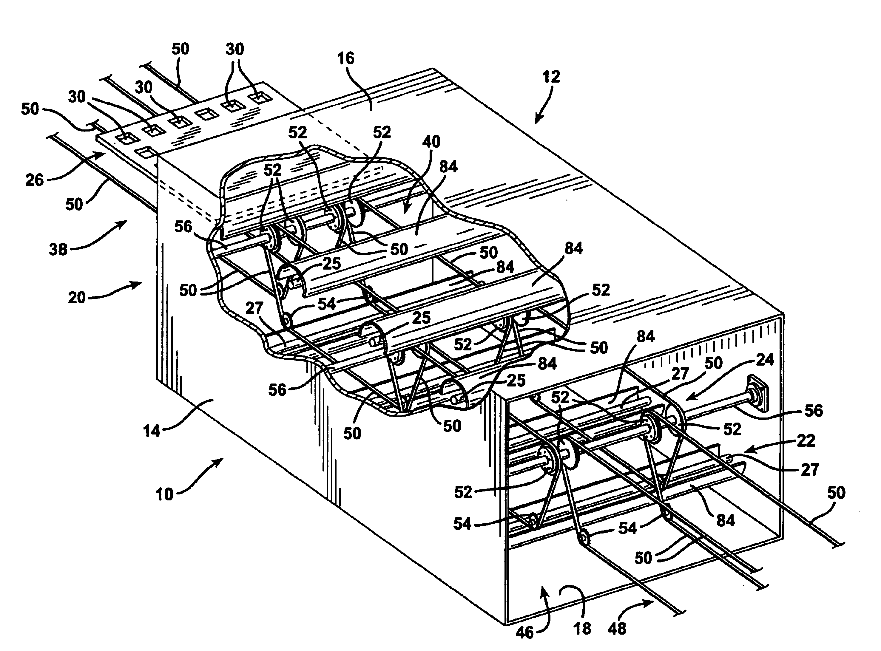
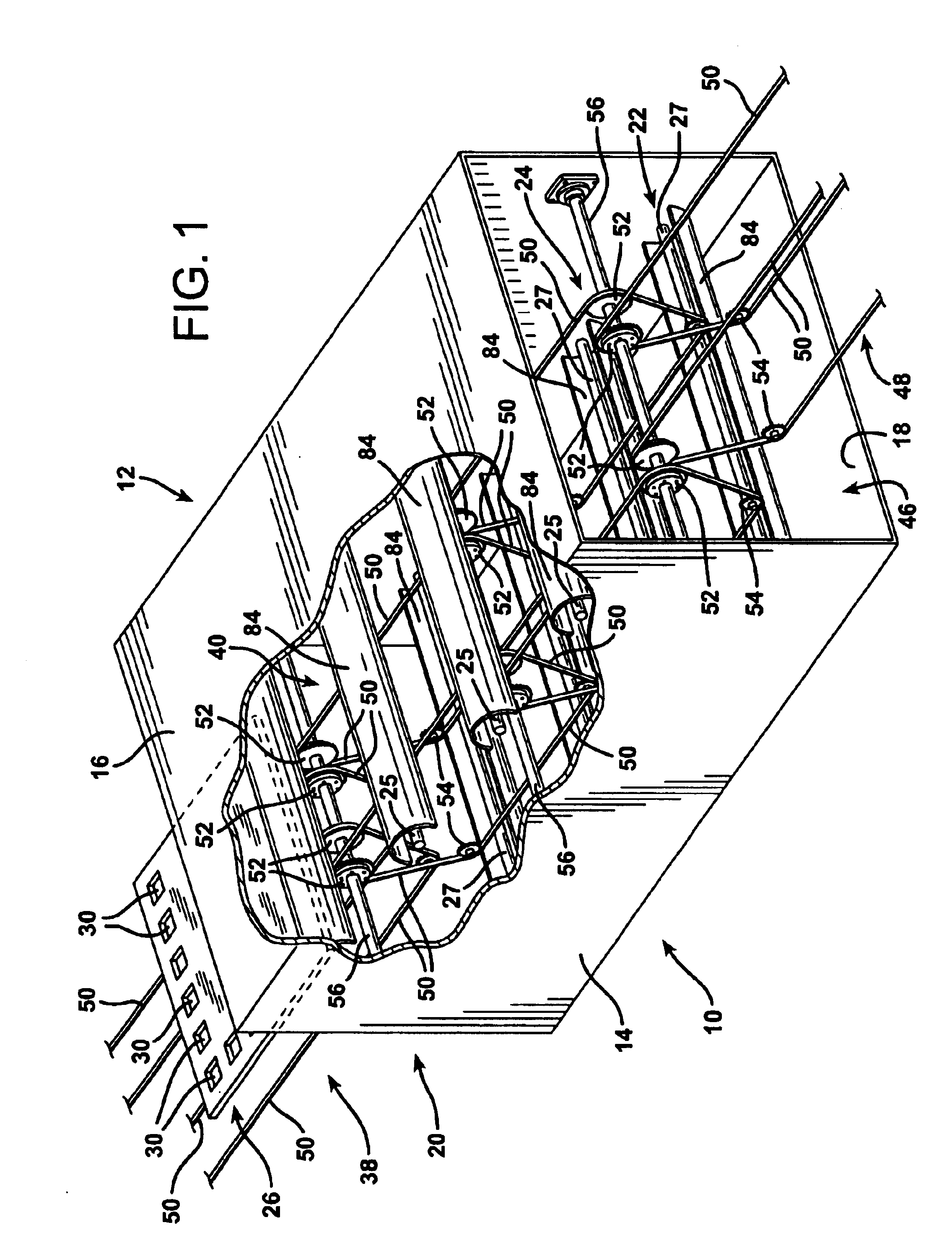
FIGS. 1 and 3 illustrate an improved ultraviolet light irradiation apparatus according to the invention indicated generally at 10. The irradiation apparatus 10 is comprised of an irradiation tunnel 12 having laterally separated vertical sidewalls 14, a roof 16, and a floor 18. The ends of the tunnel 12 have openings that define an entrance 20 and an exit 22 which are longitudinally displaced from each other.

A conveyor system, indicated generally at 24, is provided for supporting articles 26 to be irradiated with ultraviolet radiation. The articles 26 to be irradiated are supported from beneath by the conveyor system 24 and are transported along a linear, horizontal, longitudinal treatment path 28 from the entrance 20 to the exit 22 of the tunnel 12. As the articles 26 pass along the treatment path 28, they are exposed to ultraviolet radiation from above by a bank of upper ultraviolet lamps 25 and to ultraviolet radiation from beneath by a bank of lower ultraviolet radiation lamps 27...


PUM

PropertyMeasurementUnit
lengthaaaaaaaaaa
wavelengthaaaaaaaaaa
lengthaaaaaaaaaa

Abstract

The present invention involves a system for irradiating articles with ultraviolet radiation that are transported through an irradiation tunnel along a longitudinal article treatment path from a tunnel entrance to a tunnel exit employing a conveyor system. Ultraviolet irradiation sources are located within the tunnel, both above and below the article treatment path. The conveyor system includes at least two different sequential segments that contact different laterally separated locations on the articles to be treated from beneath. The points of contact between the different segments of the conveyor system are offset in a lateral or transverse direction so that all locations on the articles are left unobscured from beneath at some location on the treatment path. As a consequence, all downwardly facing surfaces of the articles carried on the conveyor system are exposed to radiation from beneath. The ultraviolet irradiation sources may be configured as elongated, transverse tubes, at least some of which are located within elliptical reflectors so that some of the ultraviolet radiation is reflected onto the passing articles at angles that vary as the articles progress along the treatment path. The ends of the ultraviolet tubes are mounted within unique end supports that allow the tubes to be rotated one hundred eighty degrees by a single person manipulating just one end of each lamp tube.

Description

1. Field of the InventionThe present intervention relates to an improved system for sterilizing articles utilizing ultraviolet radiation.2. Description of the Prior ArtAt present, food packaging products such as dairy product cartons, lids, sealing films, plastic wrap, labels, reusable product containers and other articles used in the packaging of products are sanitized by ultraviolet irradiation. In conventional food packaging and container sanitizing operations the articles to be treated are passed on a conveyor beneath a conventional lamp that emits ultraviolet radiation. The ultraviolet lamp is driven by a magnetic ballast. In order to irradiate and thereby thoroughly sanitize articles on the conveyor system the undersides of the articles resting upon the conveying mechanism must be irradiated, as well as the upper sides.To irradiate the underside of an article, it has been conventional practice to employ a conveyor belt having an open mesh through which a source of ultraviolet ...

Claims


Application Information

Patent Timeline
Patent Type & Authority Patents(United States)
IPC IPC(8): A61L2/10
CPCA61L2/10
Inventor SCHWEITZER, TODD
Owner UV DOCTOR
Why Eureka
Try Eureka