Interferometric apparatus for ultra-high precision displacement measurement

a technology of interferometry and displacement measurement, applied in the field of interferometry, can solve the problems of polarization leakage, phase measurement contamination, and change of phase difference between the two, and achieve the effect of more accurate measurements of relative displacemen

Inactive Publication Date: 2004-03-23
CALIFORNIA INST OF TECH
View PDF2 Cites 13 Cited by
  • Summary
  • Abstract
  • Description
  • Claims
  • Application Information

AI Technical Summary

Benefits of technology

It is an object of the present invention to provide

Problems solved by technology

Leakage occurs across the two otherwise independent light beams, resulting in a phenomena called polarization leakage.
When the polarization leaks from one light beam to another, the phase differences between the two are changed and the phase measurement is contaminated.
The errors arising in the phase measurement are periodic and non-linear errors.
Additio

Method used


Image

  • Interferometric apparatus for ultra-high precision displacement measurement
  • Interferometric apparatus for ultra-high precision displacement measurement
  • Interferometric apparatus for ultra-high precision displacement measurement

Examples


first embodiment

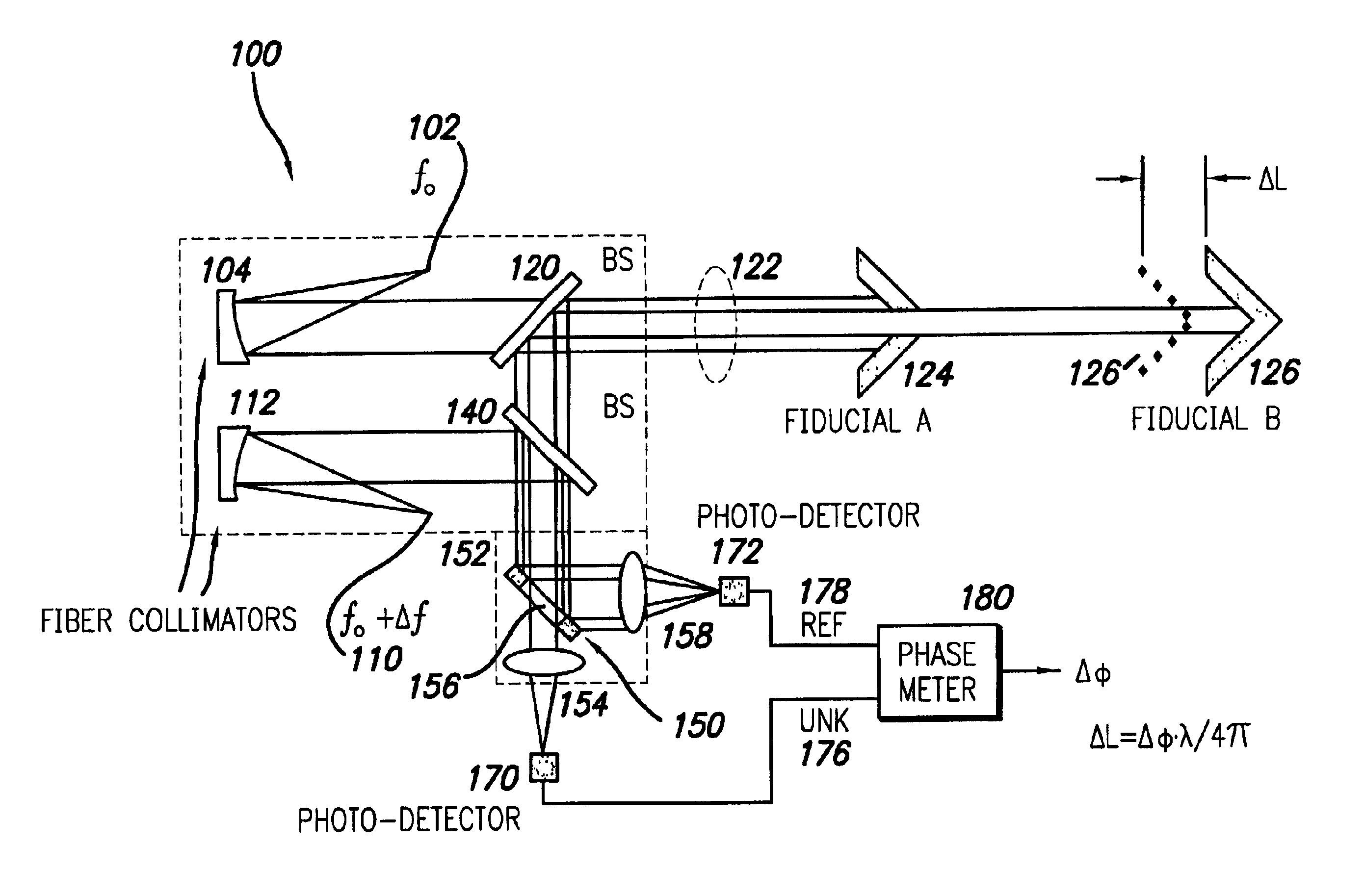
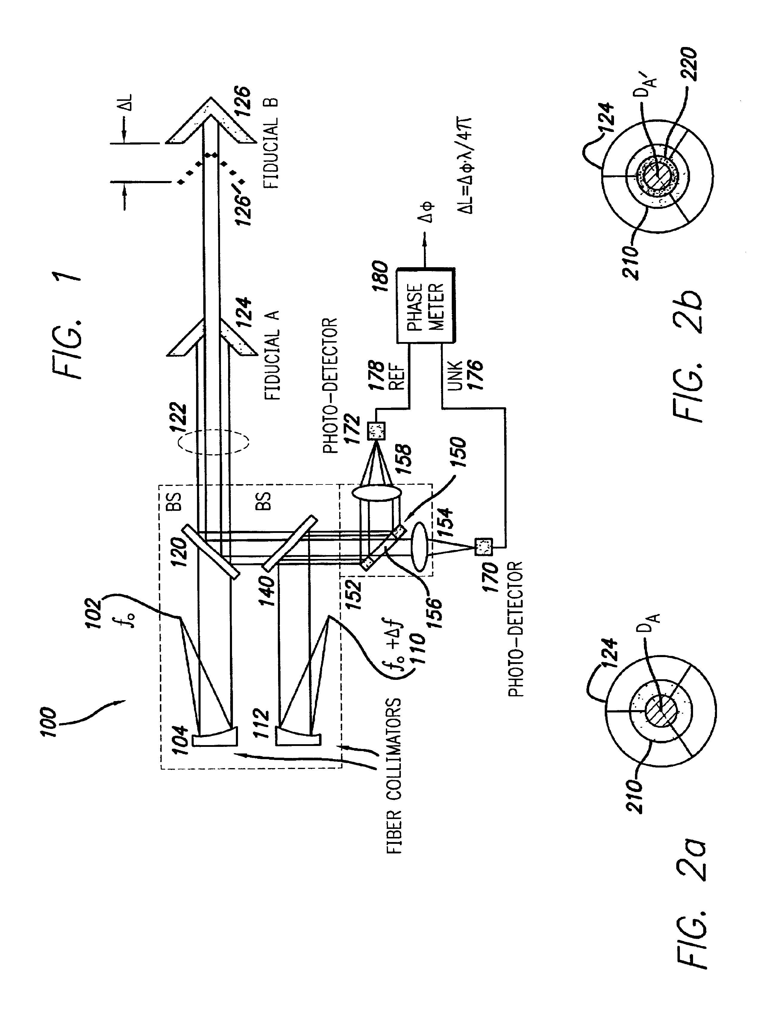
FIG. 1 shows the high precision interferometer 100 of the present invention. Light of the first wavelength f.sub.0 102 illuminates a first fiber collimator 104. Light of a second frequency, f.sub.0 +.DELTA.f, 110 illuminates a second fiber collimator 112. The light from the second source 110 at a frequency of f.sub.0 +.DELTA.f is transmitted to both photodetectors as described in more detail below. In this way, a known frequency of light is shared and is a part of both the reference signal and the reference (REF) and displacement / unknown (UNK) signals.

Light from the first light source f.sub.0 102 illuminates the first fiber collimator 104 and is transmitted to a first, or displacement, beam splitter 120. Some of this light is reflected towards the upper portion of the page showing FIG. 1 and exits out of consideration (or is discarded) for present purposes. Another portion of the light 122 is transmitted to Fiducial A 124 and Fiducial B 126. Note should be taken that reference 122 r...

second embodiment

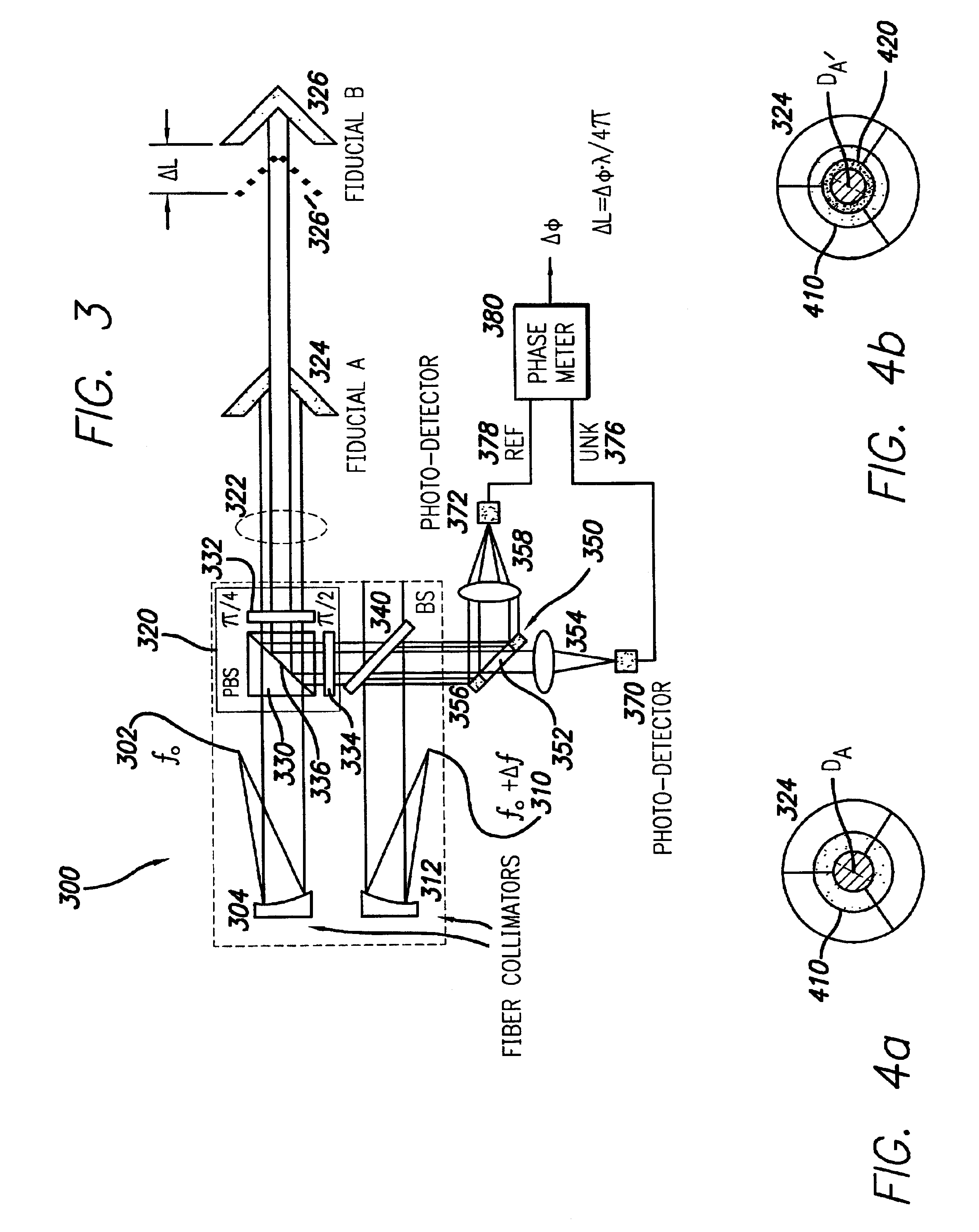
FIG. 3 shows the high-precision interferometer 300 of the present invention. FIG. 3 shows an interferometer 300 that is identical to the interferometer 100 shown in FIG. 1, except that the beam splitter 120 in FIG. 1 has been replaced by a beam splitting and polarizing system apparatus 320, having a polarizing beam splitter 330, a quarter-wave plate 332 and a half-wave plate 334. The quarter-wave plate 332 is placed between the polarizing beam splitter 330 and Fiducials A and B 324, 326. The half-wave plate 334 is placed between the polarizing beam splitter 330 and the second beam splitter 340.

Generally, the operation of the high-precision interferometer 300 of FIG. 3 is the same as that for the interferometer 100 of FIG. 1, save for the operation of the polarizing beam splitting system 320 indicated by the corresponding dotted line box.

In operation, the f.sub.0 light of the first light source 302 is transmitted to the first fiber collimator 304. The fiber collimator reflects the li...


PUM


Abstract

A high-precision heterodyne interferometer measures relative displacement by creating a thermally-insensitive system generally not subject to polarization leakage. By using first and second light beams separated by a small frequency difference (Deltaf), beams of light at the first frequency (f0) are reflected by co-axial mirrors, the first mirror of which has a central aperture through which the light is transmitted to and reflected by the second mirror. Prior to detection, the light beams from the two mirrors are combined with light of the second and slightly different frequency. The combined light beams are separated according to the light from the mirrors. The change in phase (Deltaphi) with respect to the two signals is proportional to the change in distance of Fiducial B by a factor of wavelength (lambda) divided by 4pi (DeltaL=lambdaDeltaphi1/(4pi)). In a second embodiment, a polarizing beam splitting system can be used.

Description

1. Field of the InventionThis invention relates to interferometry and more particularly to interferometric devices used for measuring relative distances between two objects.2. Description of the Related ArtInterferometry is the area of science that uses interference patterns to evaluate data such as the distance between two objects. In radio astronomy, interference patterns are generated by adding signals radiated from a star or the like. A phase difference is generated by providing the two signals from spatially-separated antennas. The longer the base line, the higher the resolving power of the radio antenna.Interferometry is used to measure short distances using laser light that is reflected and refracted in certain predictable ways. The famous Michaelson-Morley experiment is one example of this, and such devices are used in a similar fashion today. In a Michaelson interferometer, when the displacement mirror is moved, the interference pattern cyclically changes, showing the alter...

Claims


Application Information

Patent Timeline
IPC IPC(8): G01B9/02
CPCG01B9/02G01B9/02007G01B2290/45G01B2290/70
Inventor ZHAO, FENG
Owner CALIFORNIA INST OF TECH
Why Eureka
Try Eureka