

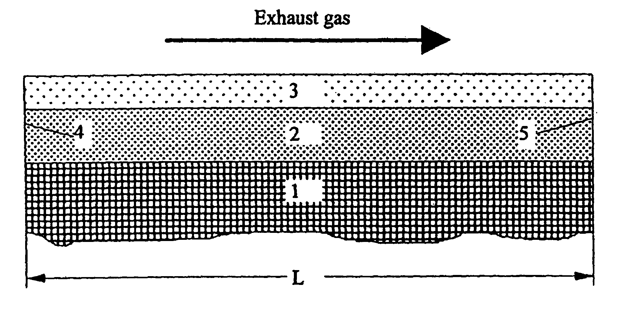
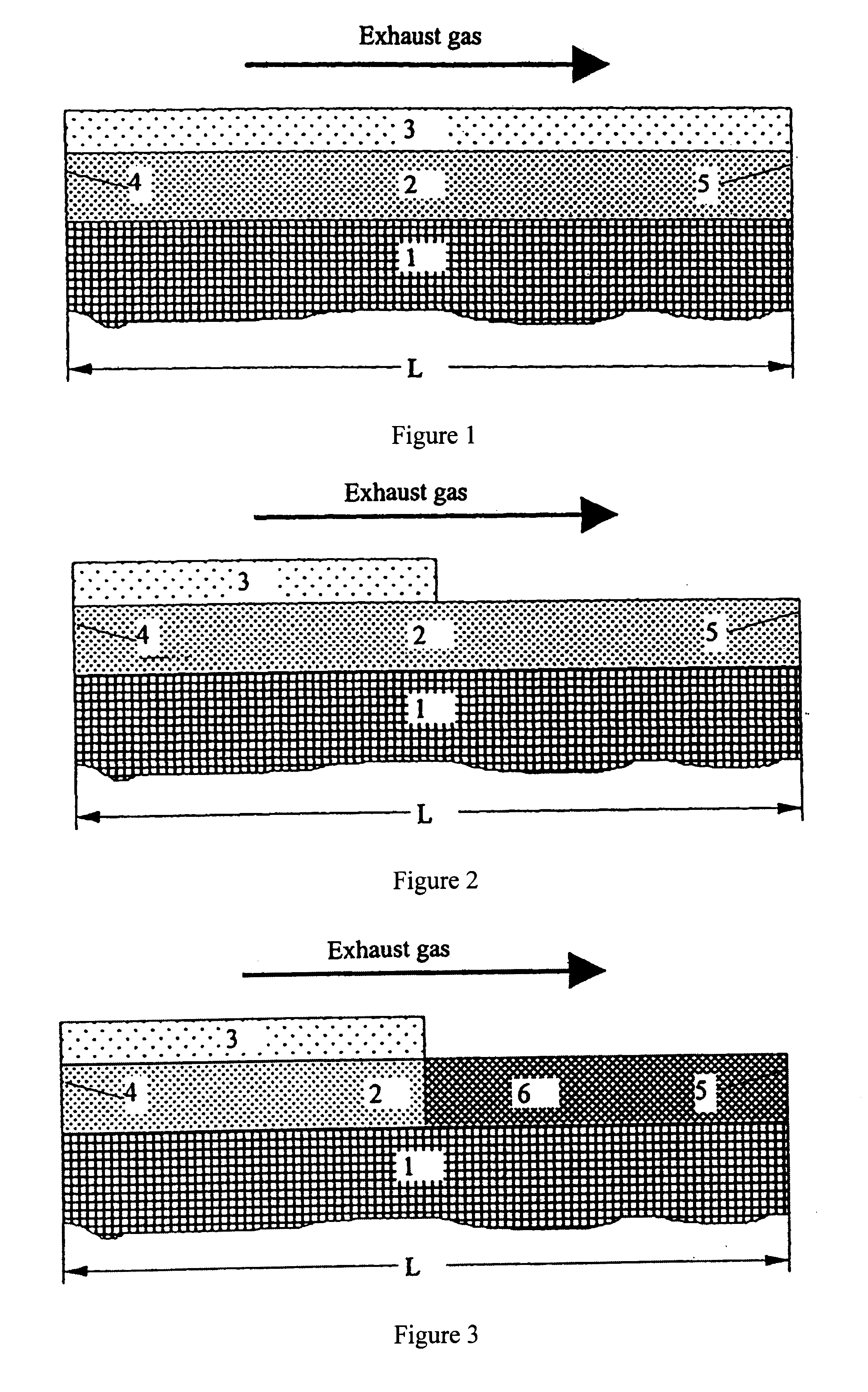
Structured catalysts for selective reduction of nitrogen oxides by ammonia using a compound that can be hydrolyzed to ammonia
a technology of ammonia and ammonia, which is applied in the direction of phosphorus compounds, cyanogen compounds, exhaust treatment, etc., can solve the problems of only being able to reduce nitrogen oxides in exhaust gas, cannot be used in conventional three-way catalysts, and only being limitedly possibl
- Summary
- Abstract
- Description
- Claims
- Application Information
AI Technical Summary
Benefits of technology
Problems solved by technology
Method used
Image

Examples
example 2
To make catalyst K2 in accordance with the invention, a titanium oxide powder was first impregnated with vanadyl sulfate corresponding to a V.sub.2 O.sub.5 content of 5 wt % by the method of pore volume impregnation. The impregnated material was dried for 15 h at 120.degree. C. and then calcined for 3 h at 400.degree. C. in air.
The resulting TiO.sub.2 / V.sub.2 O.sub.5 powder was processed with aluminum oxide to form a coating dispersion (80 wt % TiO.sub.2 / V.sub.2 O.sub.5 and 20 wt % Al.sub.2 O.sub.3) and applied in a concentration of 160 g / l to a honeycomb. The oxide coating was dried for 30 min at 120.degree. C. in a stream of air and then calcined for 1 h at 500.degree. C. in air and then calcined for 1 h at 500.degree. C. in air.
To prepare the reduction layer, the honeycomb was coated with 26 g WO.sub.3 per liter (from ammonium metasulfate) and 3 g Nb.sub.2 O.sub.5 / l (from niobium-ammonium complex) by impregnation with soluble precursors. The decomposition of the impregnated ox...
example 3
To make the catalyst K3 in accordance with the invention, TiO.sub.2 / WO.sub.3 was impregnated with a V.sub.2 O.sub.5 content of 3.2 wt % by spraying with an alkaline (pH=8 to 11) solution of ammonium metavanadate in a mixer. The resulting wet powder was then calcined in air for 3 h at 400.degree. C. Then a honeycomb support was coated with the oxide mixture of TiO.sub.2 / V.sub.2 O.sub.5 / WO.sub.3 (80 wt %) and aluminum oxide (20 wt %) (reduction layer). The amount of coating applied in this way was 180 g / l of support. The oxide coating was dried in a stream of air for 30 min at 120.degree. C. and then calcined in air for 1 h at 500.degree. C.
In another step the hydrolysis layer described in Example 1 was applied.
example 4
To make the catalyst K4 in accordance with the invention, first La.sub.2 O.sub.3 -stabilized titanium dioxide (10 wt % La.sub.2 O.sub.3) was impregnated by the pore volume impregnation method with vanadyl oxalate corresponding to a V.sub.2 O.sub.5 content of 3.2 wt % and with ammonium metatungstate corresponding to a WO.sub.3 content of 10 wt %. The impregnating material was dried for 15 h at 120.degree. C. and then calcined in air for 3 h at 400.degree. C.
Then a honeycomb support was coated with the oxide mixture of TiO.sub.2 / V.sub.2 O.sub.5 / WO.sub.3 / La.sub.2 O.sub.3 (80 wt %) and aluminum oxide (20 wt %) (reduction layer). The applied amount of coating was 180 g / l of support. The oxide coating was dried in a stream of air for 30 min at 120.degree. C. and then calcined in air for 1 h at 500.degree. C.
The hydrolysis layer described in Example 1 was applied in another step.
PUM
| Property | Measurement | Unit |
|---|---|---|
| specific surface area | aaaaa | aaaaa |
| concentrations | aaaaa | aaaaa |
| temperatures | aaaaa | aaaaa |
Abstract
Description
Claims
Application Information