
Channel selection device for receiving digital TV broadcasting, receiving device and channel selection method

a channel selection and digital tv technology, applied in the direction of automatic frequency band scanning, television systems, resonance circuit tuning, etc., can solve the problem of longer time taken to perform channel selection

Inactive Publication Date: 2004-03-30
JVC KENWOOD CORP A CORP OF JAPAN
View PDF7 Cites 20 Cited by
  • Summary
  • Abstract
  • Description
  • Claims
  • Application Information

AI Technical Summary

Benefits of technology

According to the invention, the oscillation signal creation means generates a local oscillation signal to be used for changing the frequency of the received intermediate frequency signal, and the data demodulation means demodulates data in the intermediate frequency signal whose frequency was converted by the frequency conversion means. The data reproduction means reproduces service data for providing a service from the data demodulated by the data demodulation means. The signal level detection means detects a signal level of the data demodulated by the data demodulation means, and the operation switching means decides whether the signal level detected by the signal level detection means is larger than a reference value. The signal level detection means changes the frequency of the local oscillation signal if it is decided that the signal level detected by the signal level detection means is equal to or smaller than the reference level, and performs a channel selection in a new frequency range. Accordingly, if the signal level of the data demodulated by the data demodulation means is equal to or smaller than the reference value, the next frequency range is immediately swept for a channel selection without reproducing the data for providing a service. It is therefore possible to perform a channel selection in a short time.
Accordingly, the signal level detection means can detect the signal level only when data is demodulated. By detecting the signal level quickly and switching between operations, time taken to select a channel can be shortened.
According to the invention, the oscillation signal creation step generates a local oscillation signal to be used for changing the frequency of a received intermediate frequency signal. The frequency conversion step changes the frequency of the intermediate frequency signal by using the local oscillation signal created by the oscillation signal creation step. The date demodulation step demodulates data in the intermediate frequency whose frequency was changed by the frequency conversion step. The signal level detection step detects a signal level of the data demodulated by the data demodulation step. The signal level deciding step decides whether the signal level detected by the signal level detection step is larger than a reference value. The operation switching means operate to change the frequency of the level oscillation without moving to the subsequent reproduction step, so as to sweep a new frequency range if it is decided that the signal level detected in said signal level is equal to or smaller than the reference level. The data reproduction step reproduces service data for providing a service from the data demodulated by the data demodulation step if the signal level deciding step decides that the signal level is larger than the reference level. Accordingly, if the signal level of the data demodulated by the data demodulation step is equal to or smaller than the reference value, the next frequency range is immediately swept for a channel selection without reproducing service data. Therefore, it becomes possible to remarkably shorter the time taken to sweep the whole band.

Problems solved by technology

This method is therefore associated with the problem that a time taken to perform a channel selection is longer than that for an analog channel selection.

Method used


Image

  • Channel selection device for receiving digital TV broadcasting, receiving device and channel selection method
  • Channel selection device for receiving digital TV broadcasting, receiving device and channel selection method
  • Channel selection device for receiving digital TV broadcasting, receiving device and channel selection method

Examples


Embodiment Construction

A channel selection apparatus for receiving digital TV broadcast according to an embodiment of the invention will be described in detail with reference to the accompanying drawings.

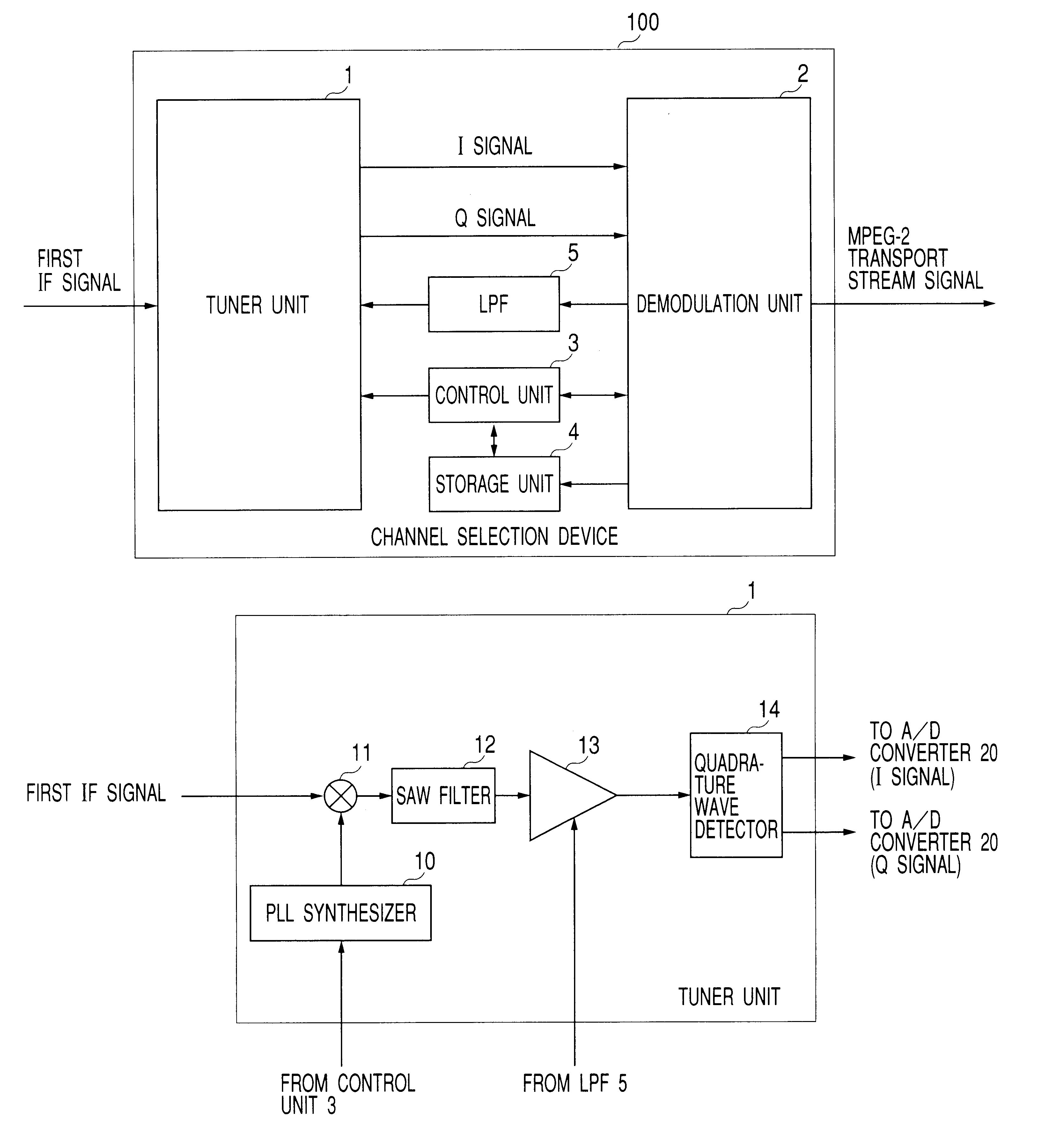
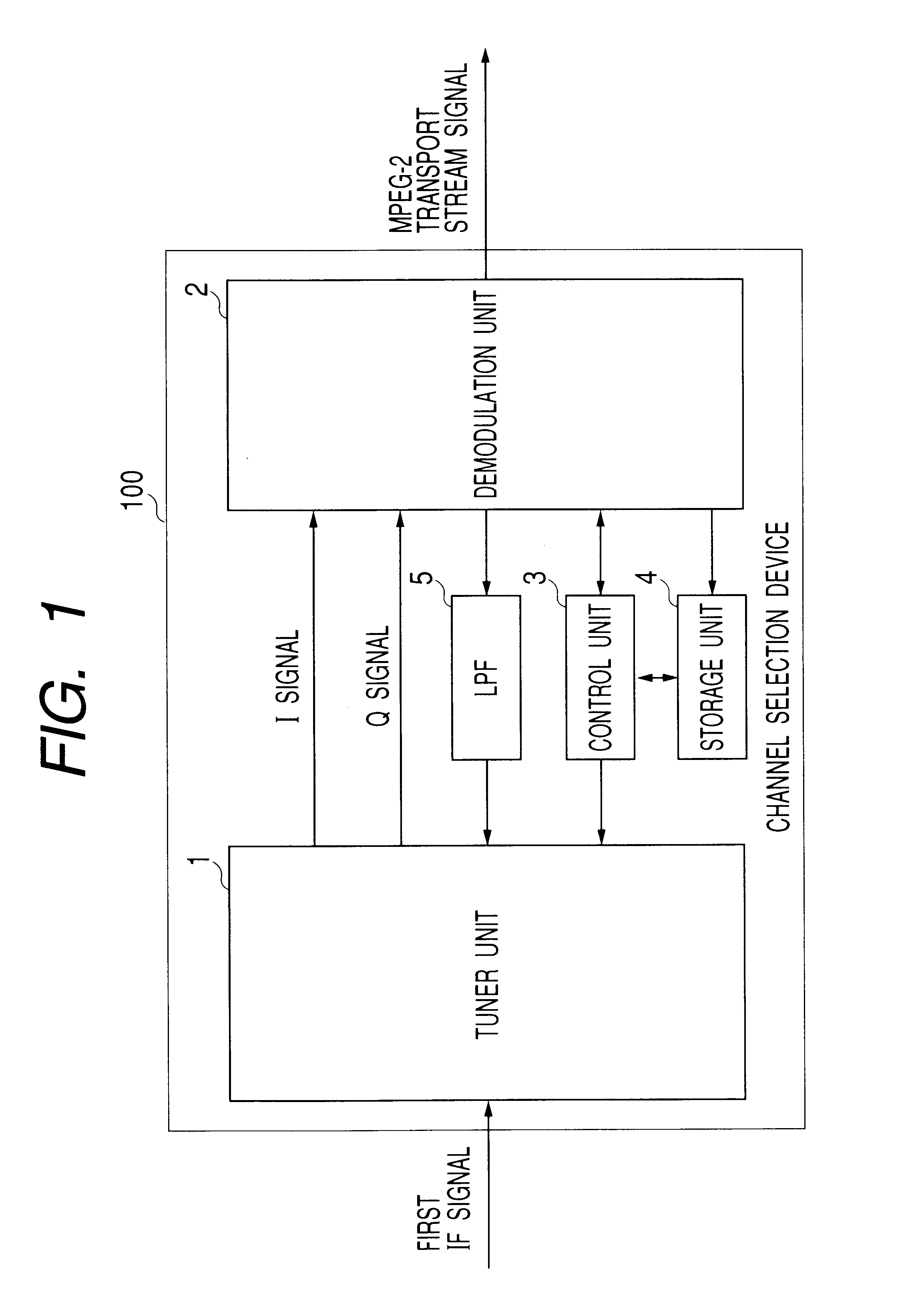
FIG. 1 is a diagram showing the structure of a channel selection apparatus for receiving digital TV broadcast (hereinafter called a channel selection apparatus).

As shown, this channel selection apparatus 100 is constituted of a tuner unit 1, a demodulation unit 2, a control unit 3, a storage unit 4 and an LPF 5.

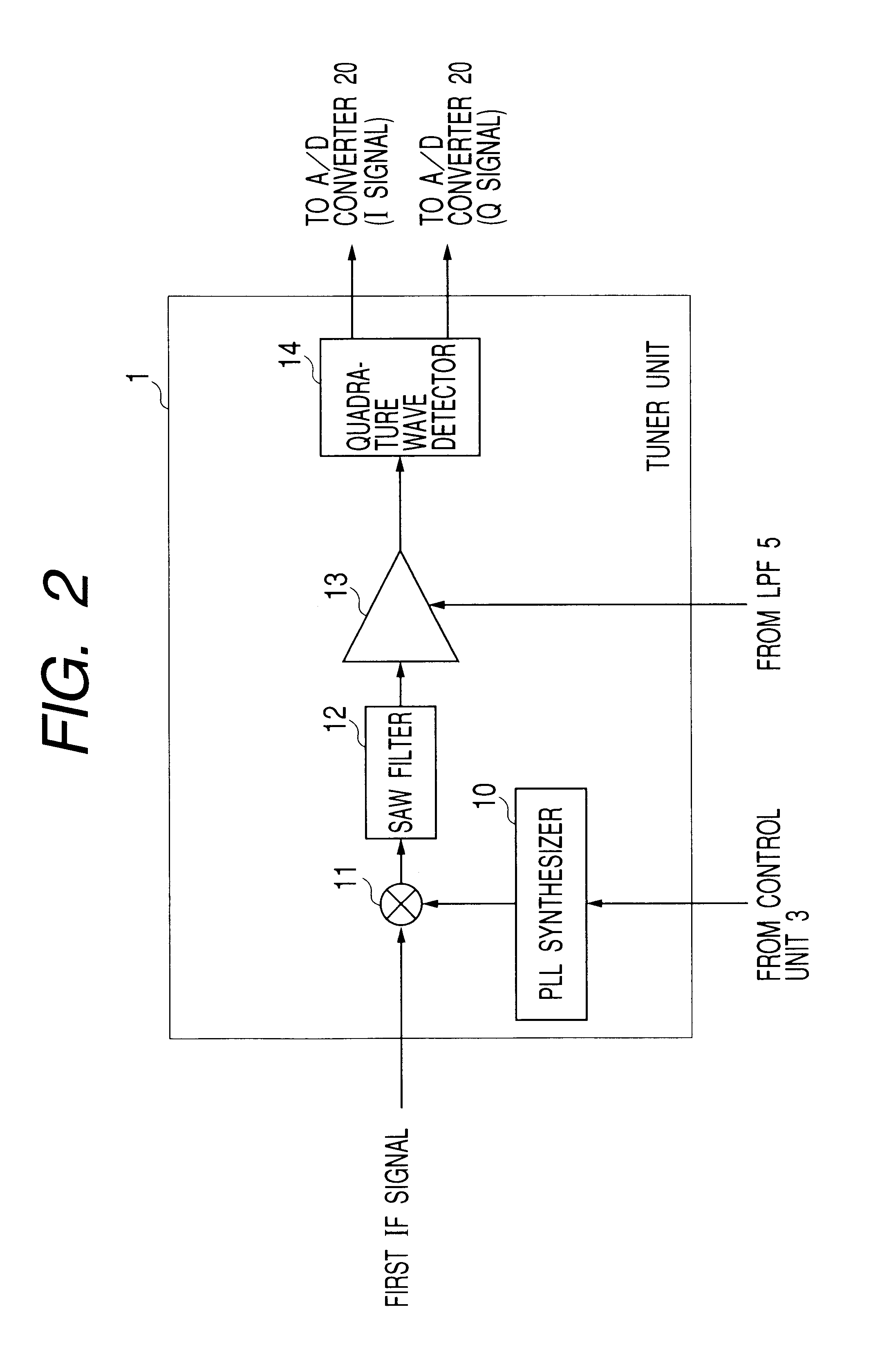
The tuner unit 1 derives in-phase components (I signal) and quadrature components (Q signal) of a baseband signal from a first IF (Intermediate Frequency) signal received by a satellite antenna or the like and frequency-converted by an LAB (Low Noise Block down converter).

As shown in FIG. 2, the tuner unit 1 is constituted of a PLL synthesizer 10, a mixer 11, an SAW (Surface Acoustic Wave) filter 12, an AGC (Automatic Gain Control) amplifier 13 and a quadrature detector 14.

The PLL synthesizer 10 is...


PUM


Abstract

A tuner unit generates a local oscillation signal which is multiplied by a received first IF signal to change the frequency of the received first IF signal, and converts the frequency-changed first IF signal into a baseband signal. A demodulation unit detects the signal level of demodulated data, and notifies the signal level to a control unit. The control unit compares the signal level notified by the demodulation unit with a reference value stored in a storage unit, and if the signal level is equal to or smaller than the reference value, makes the tuner unit change the frequency of a local oscillation signal to be used for frequency conversion of the first IF signal and perform a channel selection in a next frequency range. Time taken to start providing a service can therefore be shortened.

Description

The present invention relates to a channel selection apparatus, a receiver and a channel selection method, respectively for receiving and reproducing digital TV broadcast data by sweeping a predetermined frequency range. More particularly, the invention relates to a channel selection apparatus, a receiver and a channel selection method, respectively for receiving digital TV broadcast data, capable of starting providing services by presetting all receivable (tunable) stations in a short time.RELATED ARTA channel selection apparatus is known which sweeps a predetermined frequency range in a broadcast band and tunes in a desired channel to receive digital TV broadcast. A channel selection apparatus of this type establishes synchronization by sweeping a predetermined frequency range and derives a MPEG2 (Moving Picture Expert Group Phase 2) transport stream signal from an IF (Intermediate Frequency) signal in order to provide services.Such a channel selection apparatus for receiving digi...

Claims


Application Information

Patent Timeline
IPC IPC(8): H03J1/00H03J7/18H04N5/44H04N5/50H04N5/455
CPCH03J1/0066H03J1/0091H03J7/18H04N5/44H04N5/4446H04N5/455H04N5/50H04N5/4401H04N21/426H04N21/4263H04N21/4384
Inventor TSURUMI, ATSUSHI
Owner JVC KENWOOD CORP A CORP OF JAPAN
Learn More