HEV charger/generator unit

a charger/generator and electric vehicle technology, applied in the direction of engine-driven generators, propulsion parts, electric devices, etc., can solve the problems of affecting the service life of the battery, the substantial time needed to recharge the battery, and the loss of all batteries

Inactive Publication Date: 2004-04-20
FORD MOTOR CO
View PDF13 Cites 131 Cited by
  • Summary
  • Abstract
  • Description
  • Claims
  • Application Information

AI Technical Summary

Problems solved by technology

However, electric vehicles have limited range and limited power coupled with the substantial time needed to recharge their batteries.
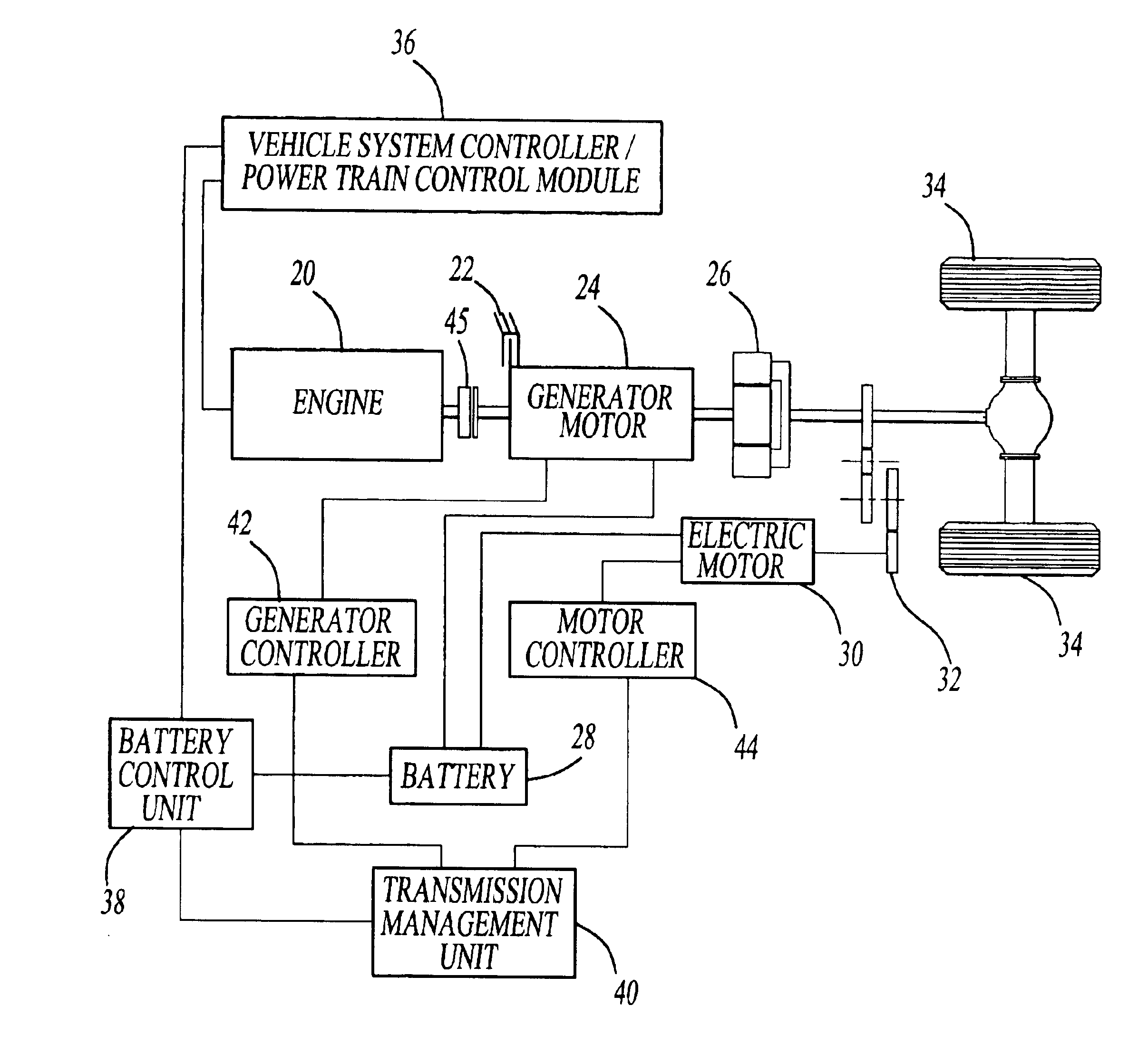
One of the main challenges associated with all HEVs is insuring enough battery charge to start and operate the vehicle.
All batteries lose charge as a result of use or lapse of time.
Generally, the HEV battery is charged by an ICE Generator in the vehicle; however, during unusual conditions or emergencies, external battery charging may be necessary.
However, these patents do not apply to HEVs because the HEV does not require an alternator.
If the onboard high voltage battery charge depletes completely, the engine would not be able to start.

Method used


Image

  • HEV charger/generator unit
  • HEV charger/generator unit
  • HEV charger/generator unit

Examples


embodiment # 1

Alternative Embodiment #1

In an alternative embodiment, the HPU utilizes vehicle to avoid component redundancy. Specifically, this embodiment provides a means for using the HEV as a "generator" without adding a separate HPU unit to the vehicle.

FIG. 4 illustrates this embodiment. A Generator 100 is connected to an engine (typically in ICE) to generate electrical power. The Generator 100 is connected to a Generator Inverter 102 which converts the AC source to DC. Both the Generator Inverter 102 and a High Voltage Battery 106 are connected to a DC Bus 104. The DC Bus 104 is also connected to a Traction Inverter 108. In a normal HEV, the Traction Inverter 108 then connects to a Traction Motor 116; however, the present invention, in an attempt to utilize the components previously described would add a Contactor 110 between the Traction Motor 116 and the Traction Inverter 108. The Contactor 110 would then be connected to a Filter 112 which is connected to a Transformer 114. The Transformer...

embodiment # 2

Alternative Embodiment #2

In a second alternative embodiment, different HEV components are used to achieve the same HPU results. FIG. 5 illustrates the second embodiment.

A Generator 130 is attached to the, engine to help generate electrical power. The Generator 130 output is feed to a Generator Inverter 132 where the electrical power is converted to DC. The Generator Inverter 132 and a High Voltage Battery 134 are connected to a high voltage DC Bus 136. The DC Bus 136 is then connected to a DC-to-DC Converter 138. The DC-to-DC Converter 138 converts the high voltage DC source to a low voltage DC source (300 volt DC to 110 volt DC). The DC-to-DC Converter 138 is then connected to an Inverter 140 to convert the DC source to AC (110 volt DC to 110 volt AC). The Inverter 140 is then connected to a Filter 142 to remove any signal noise. Finally the Filter 142 can connect to any external electric device.

In this second embodiment, power is drawn through the dedicated DC-to-DC Converter 138 ...


PUM


Abstract

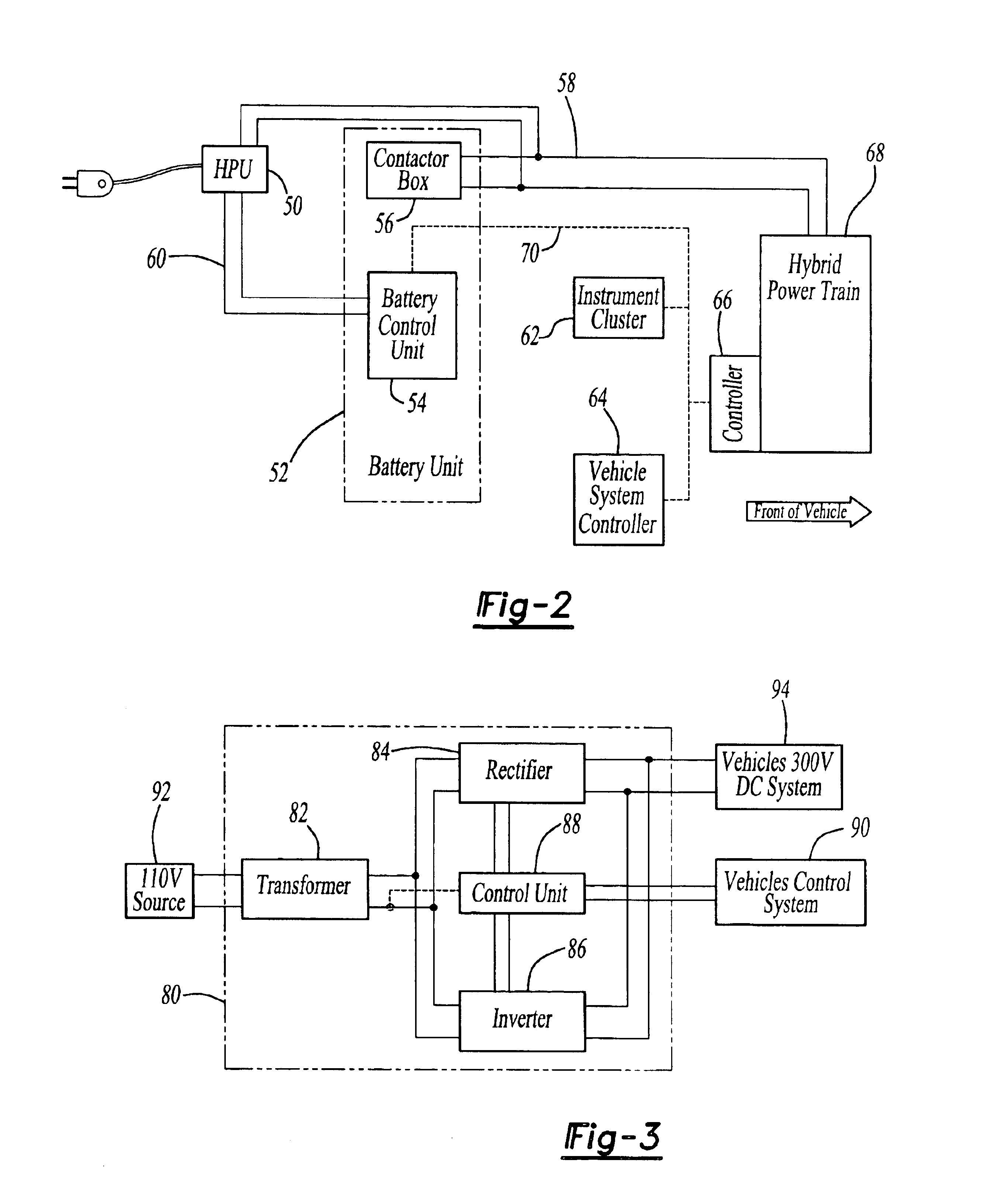
The present invention provides an apparatus, system, and method of utilizing a Home Power Unit ("HPU") which functions as a battery charger for a Hybrid Electric Vehicle ("HEV") or as a generator, utilizing the HEV's electrical power to operate external electrical devices. In its simplest form, the HPU comprises a Transformer, inverter means, rectifier means, a control unit, connection means to the HEV and external electrical loads or sources and switching means to change operation between charger and generator function. Alternative embodiments of the present invention utilize the HEV's existing components thereby avoiding component redundancy within the HPU. Specifically, in the first alternative embodiment, the inverter means are utilized within the vehicle, therefore, requiring only filter and transformer to be added to the vehicle. In the second alternative embodiment, the vehicle's DC-to-DC Converter is utilized as opposed to implementing a transformer. Therefore, only an inverter and filter are added to the system.

Description

1. Field of InventionThe present invention relates to a Home Power Unit for Hybrid Electric Vehicles ("HEVs") that acts as a general charger for the vehicle's battery and as a generator to operate external electrical devices, such as power tools.2. Discussion of the Prior ArtThe need to reduce fossil fuel consumption and pollutants of automobiles and other vehicles powered by Internal Combustion Engines ("ICEs") is well known. Vehicles powered by electric motors have attempted to address these needs. However, electric vehicles have limited range and limited power coupled with the substantial time needed to recharge their batteries. An alternative solution is to combine both an ICE and electric traction motor into one vehicle. Such vehicles are typically called Hybrid Electric Vehicles ("HEVs"). See generally, U.S. Pat. No. 5,343,970 (Severinsky).The HEV has been described in a variety of configurations. Many HEV patents disclose systems where an operator is required to select betwee...

Claims


Application Information

Patent Timeline
Patent Type & Authority Patents(United States)
IPC IPC(8): B60L1/00B60L11/12B60L11/18B60L11/02H02J7/14B60K6/00B60K6/04H02J7/00B60K6/48B60L50/15B60L50/16
CPCB60K6/48B60L11/1842B60L1/006B60L11/123B60L11/14B60L11/1814B60L11/1816B60L15/025H02J7/1415B60L1/003B60L2210/20B60L2220/54B60L2230/16Y02T10/6217Y02T10/6221Y02T10/6269Y02T10/641Y02T10/643Y02T10/7005Y02T10/7077Y02T10/7088Y02T10/725Y02T90/127Y02T90/128Y02T90/14Y02T90/163Y10S903/903Y10S903/906B60L50/16B60L50/61B60L53/14B60L53/24B60L53/305Y02T10/62Y02T10/64Y02T10/70Y02T10/7072Y02T10/72Y02T90/12Y02T90/16
Inventor GABRIEL, DAVID
Owner FORD MOTOR CO
Why Eureka
Try Eureka