
Method and device for reducing death and morbidity from stroke

a stroke and death technology, applied in the field of stroke death and morbidity reduction methods and devices, can solve the problems of inability to fully understand the exact mechanism, the cells within the infarction zone will be irreversibly damaged, and the death and disability

Inactive Publication Date: 2004-04-27
MEDCOOL
View PDF13 Cites 5 Cited by
  • Summary
  • Abstract
  • Description
  • Claims
  • Application Information

AI Technical Summary

Benefits of technology

"This patent is about a method and device for inducing localized hypothermia in the brain to prevent damage from stroke. The invention aims to address the problem of secondary ischemic injury, which is the cascade of cell injury and death caused by the inflammation and hypermetabolic response triggered by the initial damage to the brain tissue. The invention is designed to induce hypothermia in a specific area around the infarction zone, while avoiding the need for systemic hypothermia, which has its limitations and side effects. The invention also addresses the issue of intra-cranial pressure during the rewarming period after inducing hypothermia. The technical effects of the invention include reducing the risk of brain damage, improving the outcome of stroke treatment, and minimizing the risk of complications from hypothermia therapy."

Problems solved by technology

Stroke is a leading cause of death and disability.
Cells within this infarction zone will be irreversibly damaged within a few minutes.
There is a growing body of research that shows that hypothermia is neuroprotective, however, the exact mechanisms are not fully understood.
However, there was a significant complication rate, unrelated to the stroke, but due to the depth and duration of systemic hypothermia Also, it took 3.5 to 6.2 hours for the body core temperature to reach the target therapeutic temperature of 33 degrees centigrade, and it took an average of 18 hours for the body temperature to return to normal after systemic cooling was withdrawn.
However, the clinical outcome of patients studied showed no statically significant improvement in outcome over the historical controls used in this study.
Systemic hypothermia has been demonstrated to be effective in improving the outcome of ischemic stroke, however, there are several drawbacks to this approach: 1) It takes several hours to lower a patient's body to therapeutic temperatures.
This delay in achieving therapeutic temperatures allows for the progression of irreversible injury to the brain.
2) The practical therapeutic hypothermic temperature and duration is limited by the ability of the patient to tolerate, or survive the therapy.
3) The side effects of systemic hypothermia are frequent and can be life threatening, especially in frail patients.
4) The target of hypothermia therapy is the zone around the cerebral infarction, therefore inducing hypothermia systemically places the patient at undue risk.
5) During the "critical phase" (rewarming period) of hypothermia treatment, there is no effective way to manage a sudden and critical increase in intra-cranial pressure, since re-cooling the body to reverse the increase in intra-cranial pressure takes several hours.
6) Brain tissue in a zone of infarction, and in the transitional zone surrounding the infarction have substantially reduced blood perfusion rates, and brain tissues in a zone of infarction, and in the transitional zone surrounding the infarction are in a hyper-metabolic state, therefore heat generated by the hyper-metabolic processes inside the zone of infarction, and inside the transitional zone cannot be effectively dissipated by blood perfusion.
Systemic hypothermia cools a zone of infarction and surrounding transitional zone from without, and therefore cannot eliminate this temperature differential.
Also, since the scientific evidence suggests that hypothermia must be maintained for extended periods of time, there is a great risk that clots will form on the catheters and migrate into the brain leading to further episodes of stroke.
The mechanism of cooling a zone of infarction in the brain, or the surrounding transitional zone with this approach is the same as with systemic hypothermia, and does not overcome the significant limitations as described above.

Method used


Image

  • Method and device for reducing death and morbidity from stroke
  • Method and device for reducing death and morbidity from stroke
  • Method and device for reducing death and morbidity from stroke

Examples


Embodiment Construction

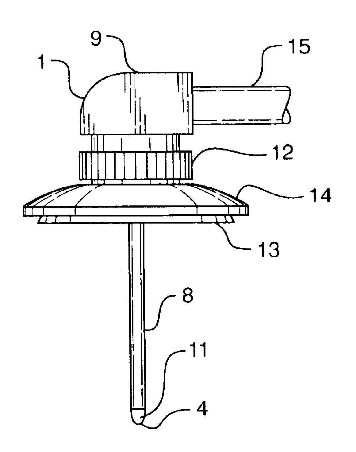
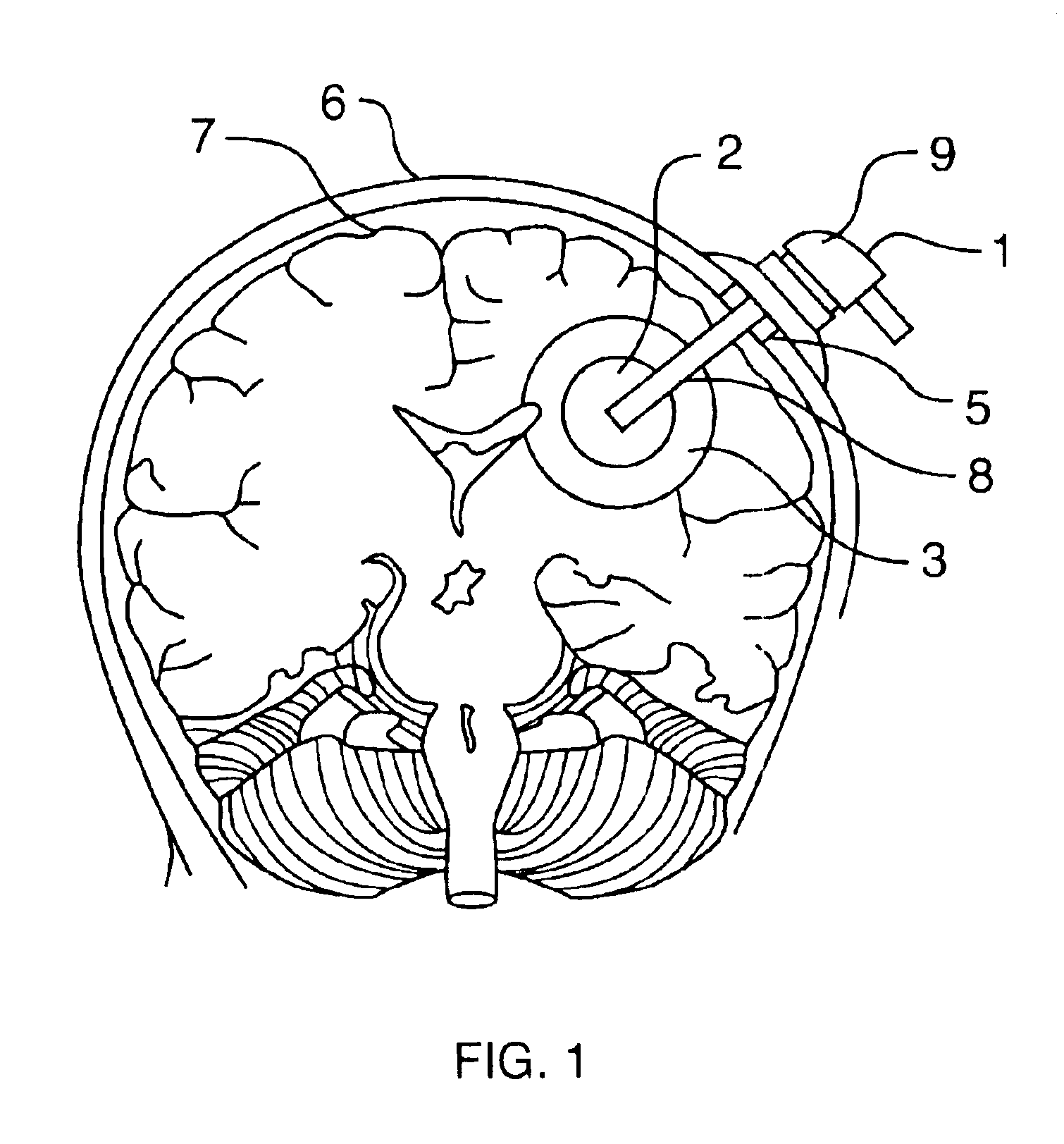
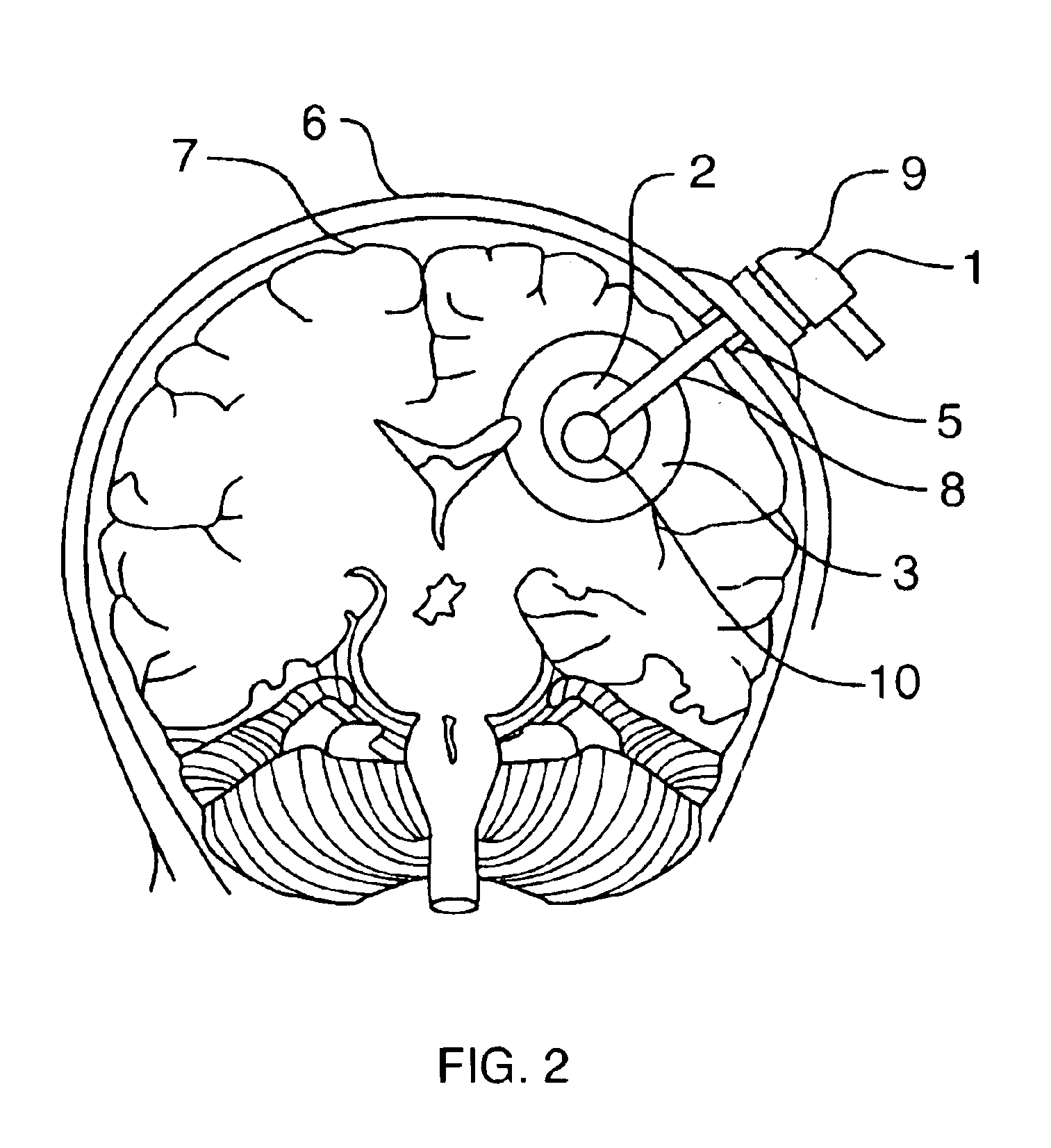
FIG. 1 depicts, in simplified form, a coronal section of the head with an interstitial brain cooling probe 1 mounted on the head 6 with the distal cooling end of the probe 4 centered in an infarcted zone of tissue 2. It will be recognized that infarctions of the brain may be nearly spherical as depicted, but are usually irregular in shape. However, this invention can be understood by referring to the simplified representation in the figures. The shaft of the probe 8 connects the distal end of the probe 4 to the proximal end of the probe 9 and passes through a surgically created hole in the skull 5. The probel is activated to cool the region surrounding the infarcted zone of tissue 3 to a temperature below 37 degrees for a period of time between 1 hour and one month. The cooling process is by heat conduction from the region surrounding the infarcted zone 3, through the infarcted zone 2, and into the distal tip of the probe 4. The temperature at the surface of the distal tip of the pr...


PUM


Abstract

Disclosed is an apparatus and method for preventing secondary ischemic injury in the brain. The apparatus includes an interstitial brain-cooling probe that is placed into an ischemic region of the brain by stereotaxic surgical technique, and a control console. The control console provides a source of cooling fluid to the interstitial brain-cooling probe, and controls the flow of cooling fluid according to signals received from a temperature sensor mounted on the interstitial brain-cooling probe. The interstitial brain-cooling probe cools an ischemic region of the brain from within the ischemic region, and cooling is substantially limited to the ischemic region. Cooling is provided for a period of time greater than one hour.

Description

Field of InventionThis invention relates to a method and device for inducing localized hypothermia in tissue, specifically brain tissue that is at risk of necrosis due to stroke.Description of Prior ArtStroke is a leading cause of death and disability. It is estimated that over 725,000 people suffer a major stroke in the United States each year, and that over 100,000 of these people die. There are two main categories of stroke: ischemic and hemorrhagic. A blockage in an artery in the brain causes ischemic stroke, and a rupture in an artery in the brain causes hemorrhagic stroke. There are approximately 600,000 ischemic stokes, and 125,000 hemorrhagic strokes in the United States each year.Within the last decade there has been a marked increase in understanding why and how brain cells die from ischemic stroke. Cells within an infarction zone have dramatically reduced blood flow of 20% of normal or less. Cells within this infarction zone will be irreversibly damaged within a few minut...

Claims


Application Information

Patent Timeline
Patent Type & Authority Patents(United States)
IPC IPC(8): A61F7/12A61F7/00A61B17/00
CPCA61F7/12A61B2017/00084A61F2007/0057A61F2007/126
Inventor LENNOX, CHARLES D.
Owner MEDCOOL
Learn More