System and method for point of use delivery, control and mixing chemical and slurry for CMP/cleaning system

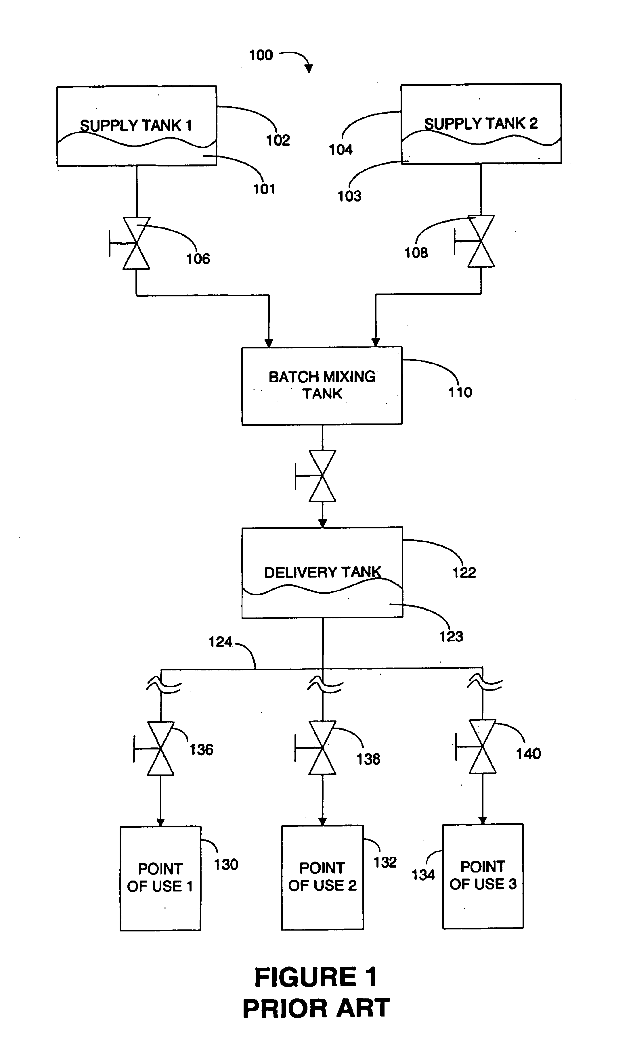
a technology of chemical mechanical planarizing and control system, applied in the direction of process and machine control, lapping machine, instruments, etc., can solve the problems of hazardous mixture 123, inefficient and typically expensive, and only use of mixture 123

Inactive Publication Date: 2004-05-04
LAM RES CORP
View PDF11 Cites 15 Cited by
  • Summary
  • Abstract
  • Description
  • Claims
  • Application Information

AI Technical Summary

Benefits of technology

Mixing the CMP chemicals, upon demand, at the point of use reduces waste and provides more accurate and consistent chemical mixtures. A point of use mixing system also allows constant feedback and control of the mixing process. Point of use mixing also reduces cost and complexity over prior-art batch mixing systems.
Point of use mixing also reduces waste by substantially eliminating mixtures produced before being required and by reducing the size of the distribution system for the mixtures.

Problems solved by technology

One of the problems with the batch process system 100 described above is that often the mixture 123 can only be used for a limited time period.
Further, the remaining mixture 123 contained in the distribution system becomes a waste product that must be disposed of which is both inefficient and typically expensive.
Yet another problem with the batch process system 100 is that often the mixture 123 is hazardous (e.g., caustic, acidic, flammable, poisonous, etc.).
The safety requirements of storing and pressurizing quantities of the hazardous mixture 123 increase the complexities of the batch process system 100 and the cost.
Therefore the batch process system 100 is more expensive and less reliable than required.
Inconsistent batches often cause inconsistent CMP process results.
Similarly, the batch process system 100 does not produce a continuous and consistent mixture.
As a result, if the mixture 123 becomes incorrect, then the CMP results could also become incorrect.
Another problem with most batch-type mixing systems is that a quantity of the mixture 123 is prepared in advance of the actual need of the mixture 123.
This results in excessive waste, which is both inefficient and typically expensive.

Method used


Image

  • System and method for point of use delivery, control and mixing chemical and slurry for CMP/cleaning system
  • System and method for point of use delivery, control and mixing chemical and slurry for CMP/cleaning system
  • System and method for point of use delivery, control and mixing chemical and slurry for CMP/cleaning system

Examples


Embodiment Construction

Several exemplary embodiments for a chemical mechanical planarization system including a point of use chemical mixing system will now be described. It will be apparent to those skilled in the art that the present invention may be practiced without some or all of the specific details set forth herein.

Point of use mixing CMP chemicals can result in more efficient use of the chemicals and reduce the waste products such as excess mixture in a mixture distribution system or excess batch-prepared mixture. In addition a point-of use mixture system can provide a continuous flow of the mixture. If the mixture is also continuously monitored, a feedback control loop can also be established to maintain a more constant mixture.

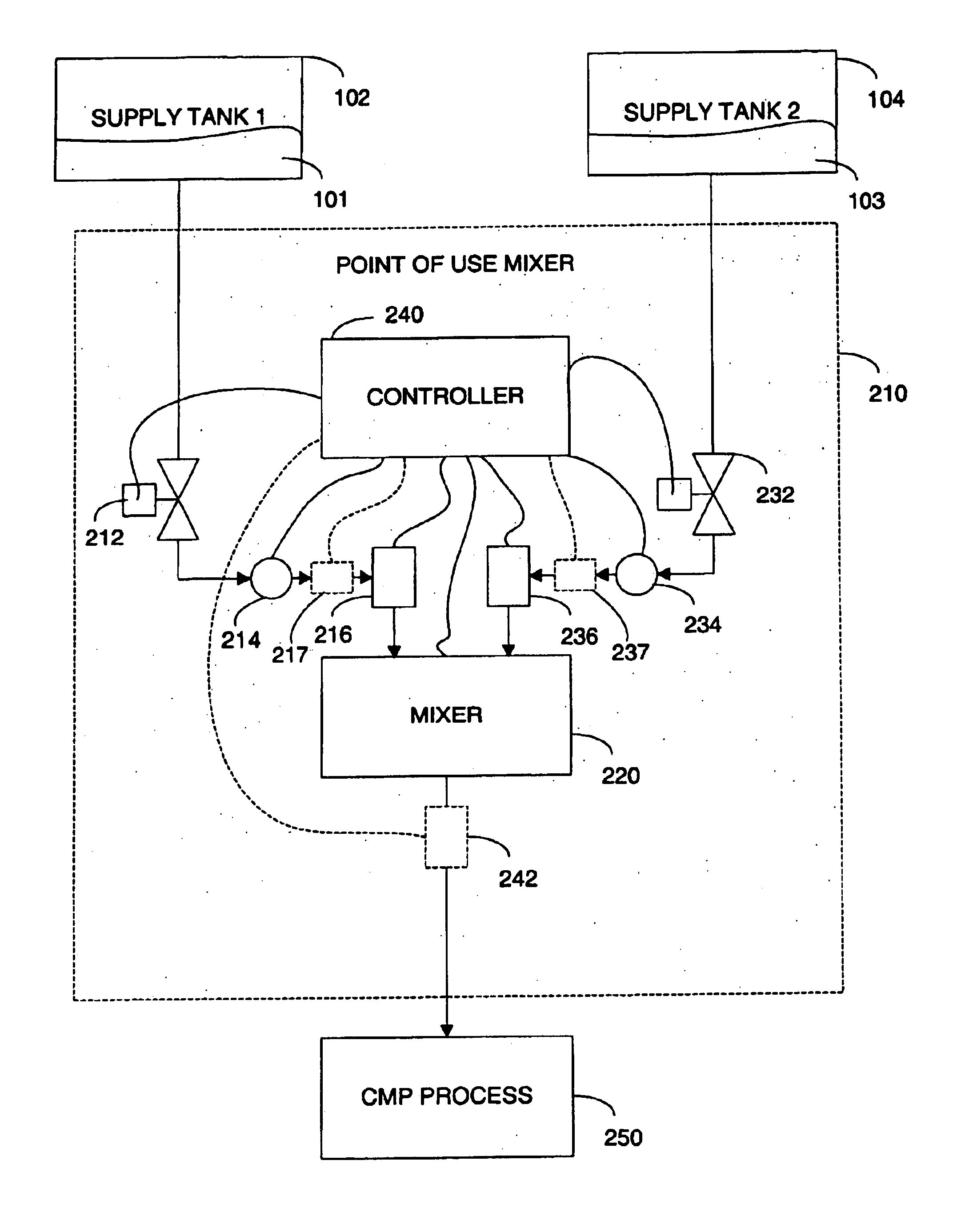
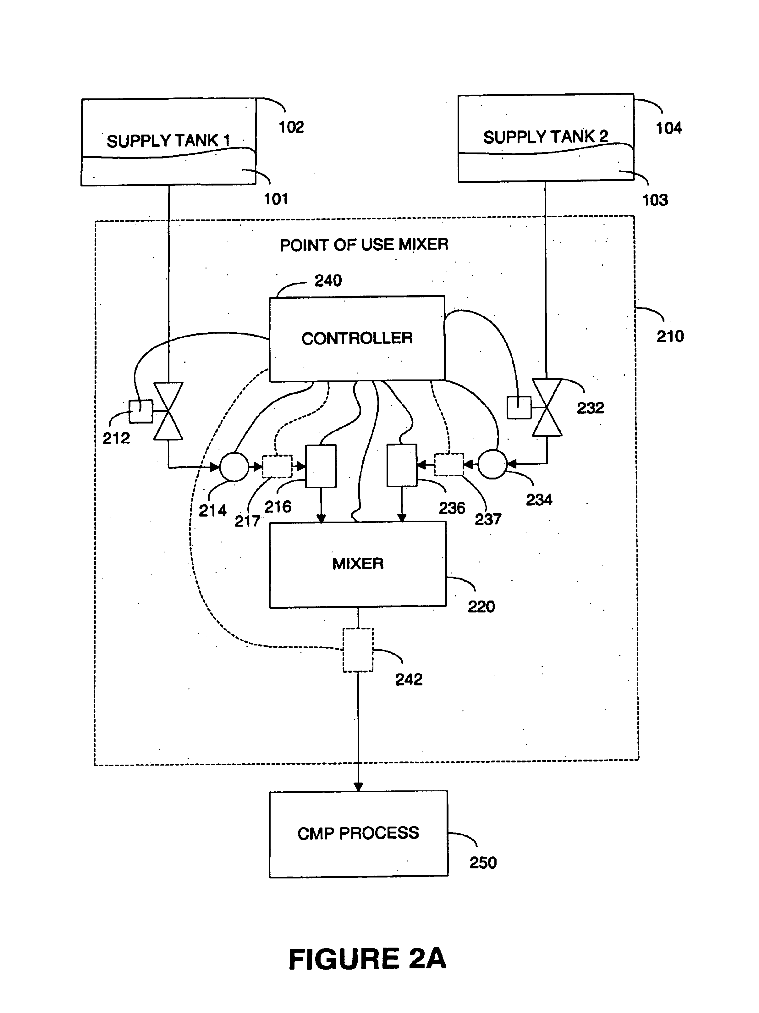
FIG. 2A is a piping and instrumentation diagram (P&ID) of a point of use mixing system 200 using two chemicals in accordance with one embodiment of the present invention. Although FIG. 2A illustrates a two chemical point of use system, the system and processes described be...


PUM


Abstract

A chemical mechanical planarization (CMP) system includes a point of use chemical mixing system. The point of use chemical mixing system includes a first and a second pump, a first and a second flow sensor, a mixer and a controller. The first pump has an input coupled to a first chemical supply and the first flow sensor coupled to the output of the first pump. The second pump has an input coupled to a second chemical supply and the second flow sensor coupled to the output of the second pump. The mixer has inputs coupled to the output of the first and second flow sensors. The controller is configured to receive signals from the first and second flow sensors and to produce control signals for the first and second pumps and the mixer. The controller is further configured to cause a mixture of the first and second chemicals upon a demand from the CMP process.

Description

1. Field of the InventionThe present invention relates generally to semiconductor wafer planarizing, and more particularly, to methods and systems for controlling and mixing chemicals for a chemical mechanical planarizing process.2. Description of the Related ArtIn the fabrication of semiconductor devices, there is a need to perform a variety of substrate preparation and fabrication operations including chemical mechanical planarization (CMP) operations, substrate cleaning, substrate polishing and buffing, substrate rinsing and drying, and other similar operations. Planarization, polishing, and cleaning operations are routinely performed on semiconductor wafers at various stages in the fabrication process. Typically, such operations are efficiently combined within process systems that are configured, for example, to receive batches of wafers at a time to be processed through CMP, polishing, buffing, cleaning, rinsing, and / or drying, followed by wafer processing through subsequent wa...

Claims


Application Information

Patent Timeline
Patent Type & Authority Patents(United States)
IPC IPC(8): G05D11/00G05D11/13B24B37/00B24B57/02H01L21/304
CPCG05D11/132G05D11/00
Inventor PHAM, XUYENNGUYEN, TUANQUACH, VIENZHOU, REN
Owner LAM RES CORP
Why Eureka
Try Eureka