Cutting tool with hardened tip having a tapered base

a cutting tool and tapered base technology, applied in the direction of cutting machines, manufacturing tools, slitting machines, etc., can solve the problems of reducing the quality of tungsten carbide of which the insert is made, the steel of the tool on the machine used to remove the upper surface of an asphalt highway can become so eroded, and the use of tools will be soon. , to achieve the effect of improving the quality of tungsten carbide, improving the brazing strength, and easy heating by induction heating

Inactive Publication Date: 2004-05-25
THE SOLLAMI COMPANY
View PDF7 Cites 195 Cited by
  • Summary
  • Abstract
  • Description
  • Claims
  • Application Information

AI Technical Summary

Benefits of technology

Briefly, the present invention is embodied in a tool having an improved cutting tip resulting in the reduction of damage to the tool body by virtue of wash away and a reduction of tool failure as a result of defects in the braze joining the tungsten carbide tip to the tool body. The tool includes a tool body having a longitudinal axis, a tapered cutting portion symmetric abound the axis, a radial flange behind the cutting portion, and a cylindrical shank behind the radial flange. The shank of the cutting tool is sized to be received within a cylindrical tool holder mounted on the machine. The tapered cutting portion of the tool body has a seat at the forward end thereof and brazed into the seat is an insert in accordance with the present invention.
In another preferred embodiment the tool body has a seat in the forward end and an insert in the seat, the insert and seat being configured as described above with respect to the first embodiment. Surrounding the seat is an annular groove coaxial with the axis of the seat, and brazed into the annular groove is an annular tungsten carbide collar. The annular collar which extends around the base of the cutting insert serves as a shield that protects the tool body from the ravages of wash away and therefor extends the life of the tool. The collar can be of a different hardness than the insert and the braze material used to retain the insert in the seat can have different properties from the braze material used to retain the collar in the annular groove.
The tapered configuration also permits the burping out of steam and other gases. Small amounts of water permeate the flux needed to properly braze the parts. As the parts are heated to melt the braze, the moisture turns to steam and unless the steam can be released, it forms a pocket between the surfaces of the base and the seat, ejecting the carbide insert from the seat. Where the outer surface of the base is tapered, the steam can push the insert outward of the seat and escape between the outer surface of the base and the inner surface of the seat as a burp. In similar fashion the tapered configuration allows flux and excess braze to escape during the brazing process. The tapered configuration of the base and the seat also allows the tungsten carbide insert to forge of flatten the dings and nicks at the mouth of the seat during one of the final manufacturing steps in which the insert is pneumatically pressed into the metal body that has been heated to forging temperature.
The tapered contour of the inner wall of the seat results in a thicker steel wall at the base of the seat than at the top, thereby providing for a stronger seat for retaining the tungsten carbide insert. Another benefit results from the fact that an oscillating magnetic field generated by an induction heater is used to braze the parts together. During the brazing process a wafer or slug of braze material is placed in the seat of the tool body under the rear surface of the insert, and the parts are then subjected to the oscillating magnetic field of the induction heater. The steel of the tool body is electrically magnetic and, therefore, it is heated by the oscillating magnetic force field. Heat from the steel body melts the wafer of braze material. Except for the cobalt or nickel, which make up only a small portion of the amalgamation of metals within the insert, the tungsten carbide is slightly magnetic and is only slightly heated by the induction heater. Where the wall of the seat has a taper in accordance with the present invention, the wall surrounding the base of the insert is thicker than the walls of all prior art seats and, therefore, it is more readily heated by induction heating. The steel is therefor heated faster and to higher temperatures than was the case during brazing of prior art inserts into their corresponding seats.
Where the insert is surrounded by an annular collar, the seat for the insert and the annular groove for retaining the collar are machined into the forward end of the tool body leaving a tubular protrusion. The inner wall of the tubular protrusion is the inner wall of the seat for retaining the conical insert and the outer wall of the protrusion is the inner wall of the groove for retaining the collar. The steel protrusion therefor separates the tungsten carbide of the insert from the tungsten carbide of the collar. Capillary action for the braze material is better with steel than with tungsten carbide so the steel draws the liquefied braze material between the parts. The braze material also bonds more strongly and more readily to steel than to tungsten carbide and therefor the steel protrusion improves the brazing strength retaining both the insert and the collar.
The quality of the tungsten carbide of which the insert is made is improved by the better compacting of the particles prior to sintering. The frustoconically shaped body of the insert of the present invention results in better powder flow during the manufacture of the insert which causes a more dense compaction of the particles than a cylindrical insert because the tapered walls apply compressive forces at 90 degrees to the walls of the die against the particles while they are being forced into the die. The final product is less subject to breakage than prior art inserts because the steel tubular sleeve, positioned between the inner and outer tungsten carbide portions, provides more resiliency along its entire length adjacent to the insert.

Problems solved by technology

As the machine cuts away hard material, the tools become worn.
In the summer months, especially in the southern states, the steel of tools on machines used to remove the upper surfaces of an asphalt highway can become so eroded by wash away that the forward end of a tool takes on an hourglass contour.
An hourglass contour is one which the tool body is narrower at its midsection than it is at either the end mounted in the tool holder or the end holding the cutting insert, such that further use of the tool will soon result in failure.
After the cutting tools of the machine become worn, the machine must be taken out of service and the tools replaced, a process which consumes a considerable amount of time, and it is not uncommon in warmer states to replace the tools of a machine two or three times during the course of a single working day.
A common cause of tool failure is the braze which binds the tungsten carbide insert into the seat at the forward end of the tool body.
A certain percentage of all tool failures are the result of defects in the braze causing the tungsten carbide insert to fall out of the tool body before either the tool body or the insert has become sufficiently worn to be taken out of service.

Method used


Image

  • Cutting tool with hardened tip having a tapered base
  • Cutting tool with hardened tip having a tapered base
  • Cutting tool with hardened tip having a tapered base

Examples


Embodiment Construction

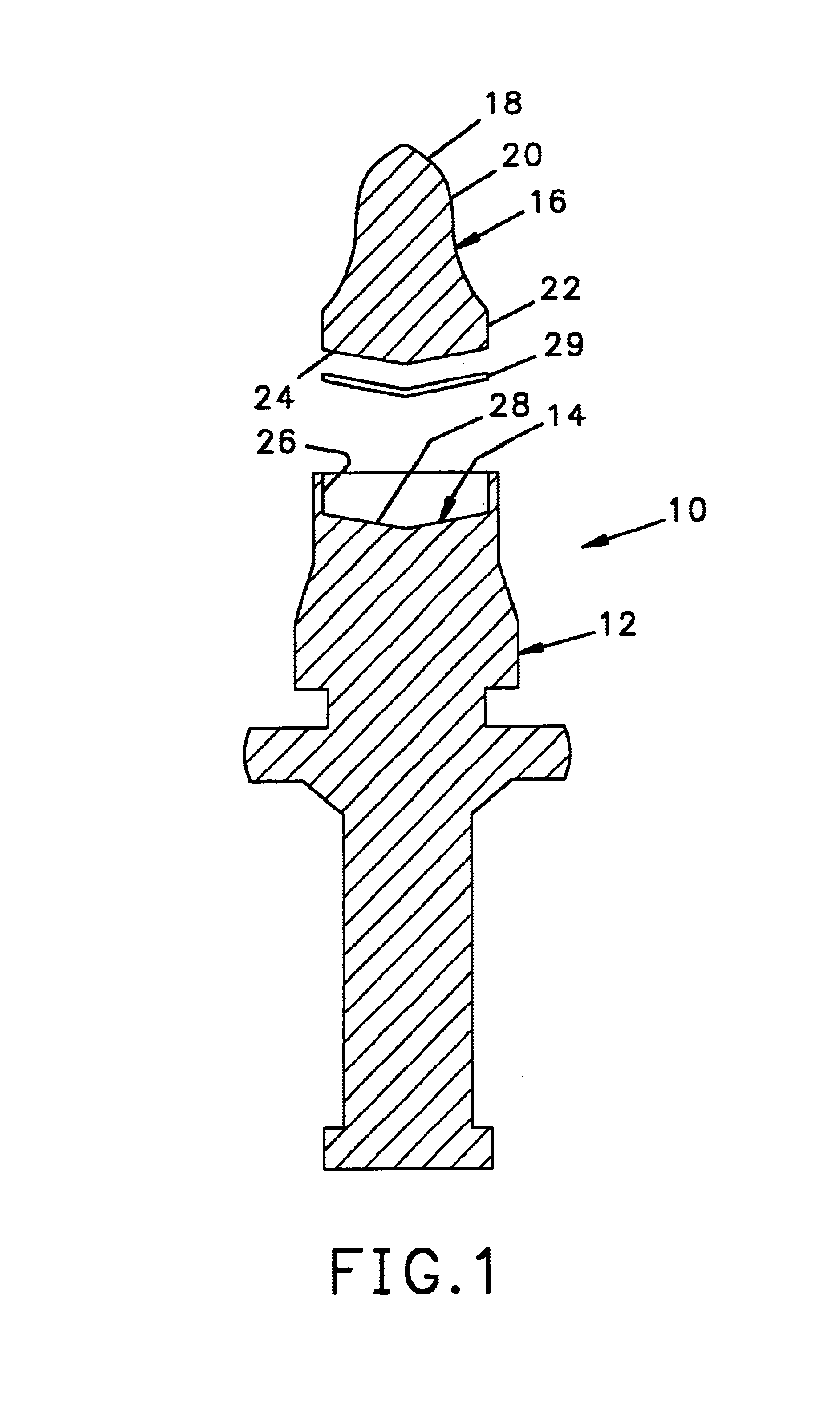
Referring to FIG. 1, a tool 10 in accordance with the prior art includes a tool body 12 having a seat 14 at the forward end thereof and an insert 16 brazed into the seat 14. The insert has a conical forward cutting end 18, a tapered midsection 20 and a generally cylindrical base 22 with a conical rear surface 24. The base 22 of the prior art insert 16 is fitted into the complementary shaped seat 14 which in turn has a cylindrical inner wall 26 complementary to the cylindrical base 22 and a bottom surface 28 complementary to the rear surface 24 of the insert 16 and is retained by braze material 29.

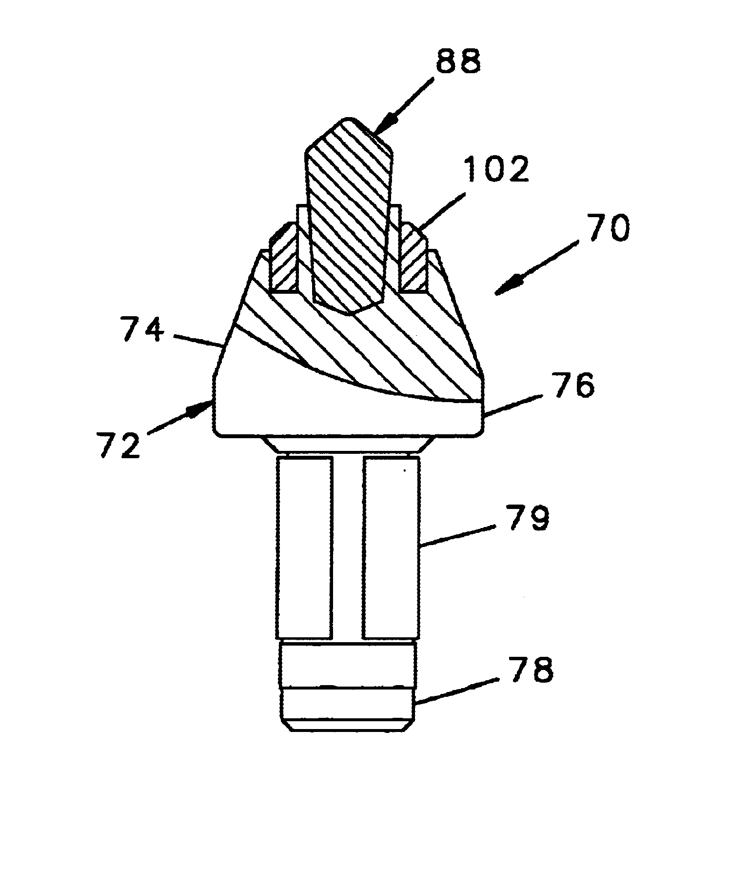
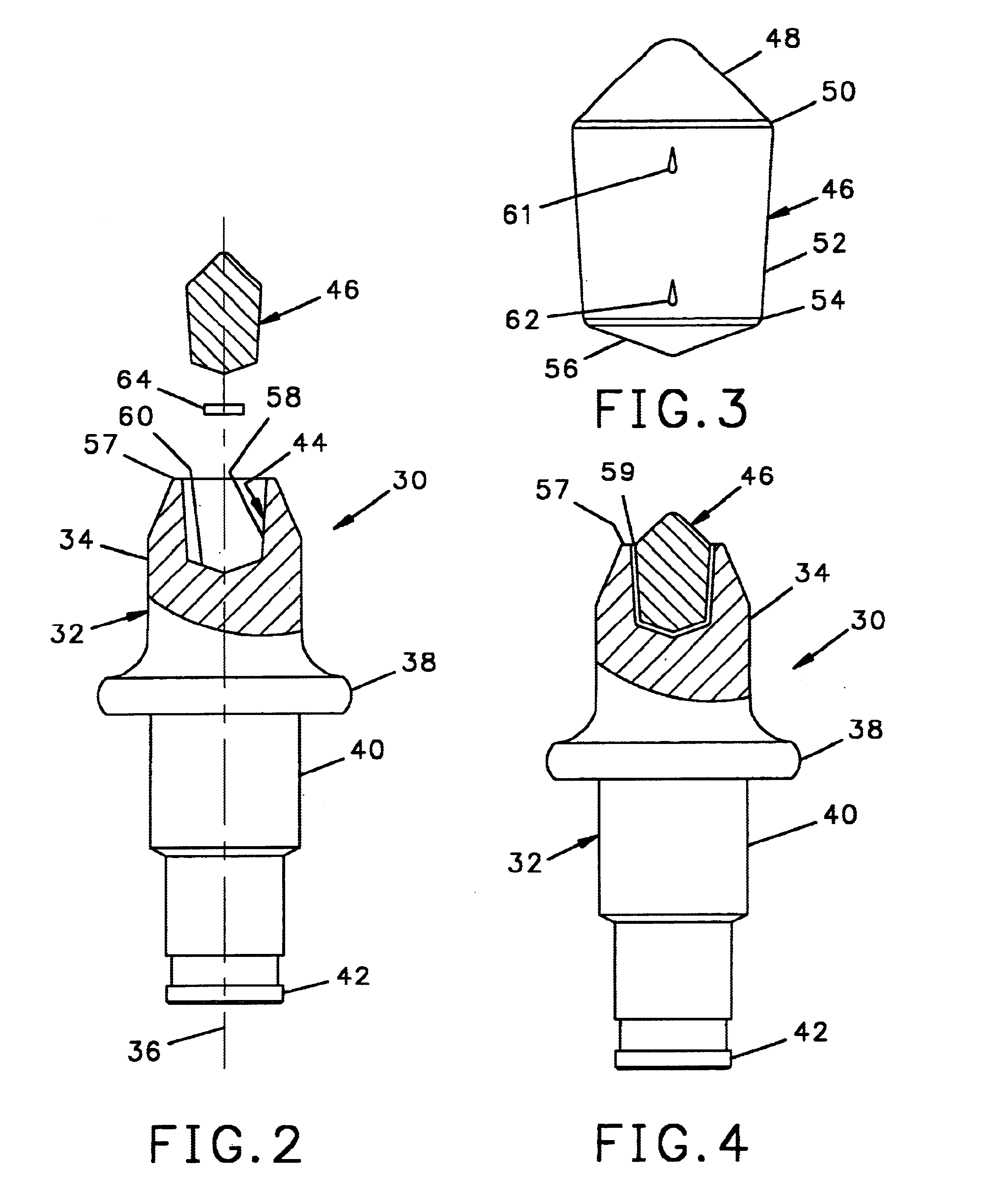
Referring to FIGS. 2, 3 and 4, a tool 30 in accordance with the present invention has a tool body 32 having a rotationally symmetric forward portion 34 defining an axis 36 and axially aligned behind the forward portion 34 is a radial flange 38. Axially behind the radial flange 38 is a cylindrical shank 40 having a hub 42 at the distal end thereof, the hub 42 having a diameter greater than t...


PUM

PropertyMeasurementUnit
distanceaaaaaaaaaa
diameteraaaaaaaaaa
hardaaaaaaaaaa

Abstract

A cutting tool has a centrally located tungsten carbide insert brazed into a seat at the forward end of the tool. The seat has a circular mouth and rearward of the mouth is a frustoconical inner wall. At the bottom of the seat is a transverse surface. A tungsten carbide insert is brazed into the seat and the base of the insert is complementary in shape to the seat. A second annular insert may also be brazed into a complementary shaped annular seat that surrounds the centrally located seat.

Description

The present application relates to cutting tools having hardened tungsten carbide tips and, in particular, to a new tip having a tapered base, that is a base having a large forward diameter complementary to the diameter of the mouth of the seat of the tool and a smaller rearward diameter recessed in the seat.BACKGROUND OF THE INVENTIONMachines used to cut hard surfaces such as asphalt and concrete have a plurality of tools mounted on a wheel or drum which is forced against the surface to be broken. Each tool has an elongate steel body at the forward end of which is a tungsten carbine insert for breaking up the hard surface to be cut. The tools are mounted in tool holders on the wheel or drum such that the tools move through a circular orbit as the wheel rotates with each tip penetrating the hard surface and removing a small amount of material to thereby advance the cut.As the machine cuts away hard material, the tools become worn. The hardened cutting tip at the forward end of the t...

Claims


Application Information

Patent Timeline
Patent Type & Authority Patents(United States)
IPC IPC(8): B28D1/18E21C35/18E21C35/00
CPCB28D1/188E21C2035/1806E21C35/1831
Inventor SOLLAMI, PHILLIP A.
Owner THE SOLLAMI COMPANY
Why Eureka
Try Eureka