Optical module and optical communication system

a technology of optical communication system and optical module, which is applied in the field of optical modules, can solve the problems of large optical loss, high cost of welding method, and high thermal resistance of optical parts and adhesives, and achieve the effects of low cost, low cost, and reliable supply of conductivity

Inactive Publication Date: 2004-05-25
OCLARO JAPAN INC
View PDF8 Cites 35 Cited by
  • Summary
  • Abstract
  • Description
  • Claims
  • Application Information

AI Technical Summary

Benefits of technology

An object of the present invention is to provide an optical module which uses a ceramic package, and is characterized by the following: low cost; an optical part is not damaged; and the metal cap can be secured while conductivity is reliably provided. According to the present invention, it is possible to provide, at low cost, an optical module that operates at super-high speed of 10 Gbit / s class, and that has an excellent EMC property.
As a background of the present invention, the conventional methods have the following disadvantages:
In addition, if the metal cap is secured by solder jointing which is the second method, heating at about 200.degree. C. is required. This produces a problem of thermal resistance of an optical part and an adhesive. For example, in an optical module having a pigtail of an optical fiber, heating changes the quality and shape of a sheath (nylon, etc.) of the fiber. In the worst case, an imposed stress causes microbending in a core wire of the fiber, resulting in a large optical loss. An optical module on which an optical connector for inputting and outputting a light signal is mounted also uses an adhesive made of epoxy, etc. to secure a ferrule constituting a connector to a module. Therefore, it has the following disadvantages: if the optical module is heated at about 200.degree. C., the adhesive degrades, leading to a decrease in bond strength; and fitting the connector into the optical module, and taking the connector out from the module, increase an optical loss of the connector.
As the cap, a metal cap, or a cap having a conductive film on its surface, is used. As a base material of the cap, besides metal, for example, ceramic may also be used, and a conductive film may be formed on its surface. Electrically connecting the lid having conductivity to the terminal which is connected to a ground permits the lid to function as an electromagnetic shield. Thus, degradation in property of the module caused by circumferential electromagnetic noise can be prevented, and emission of electromagnetic noise from the module can also be prevented.

Problems solved by technology

Therefore, the cost of the welding method is extremely high, which is a disadvantage to be considered.
This produces a problem of thermal resistance of an optical part and an adhesive.
In the worst case, an imposed stress causes microbending in a core wire of the fiber, resulting in a large optical loss.
Therefore, it has the following disadvantages: if the optical module is heated at about 200.degree. C., the adhesive degrades, leading to a decrease in bond strength; and fitting the connector into the optical module, and taking the connector out from the module, increase an optical loss of the connector.

Method used


Image

  • Optical module and optical communication system
  • Optical module and optical communication system
  • Optical module and optical communication system

Examples


first embodiment

A first embodiment concerns an optical module having an LD element and a PD element that monitors output of the LD element.

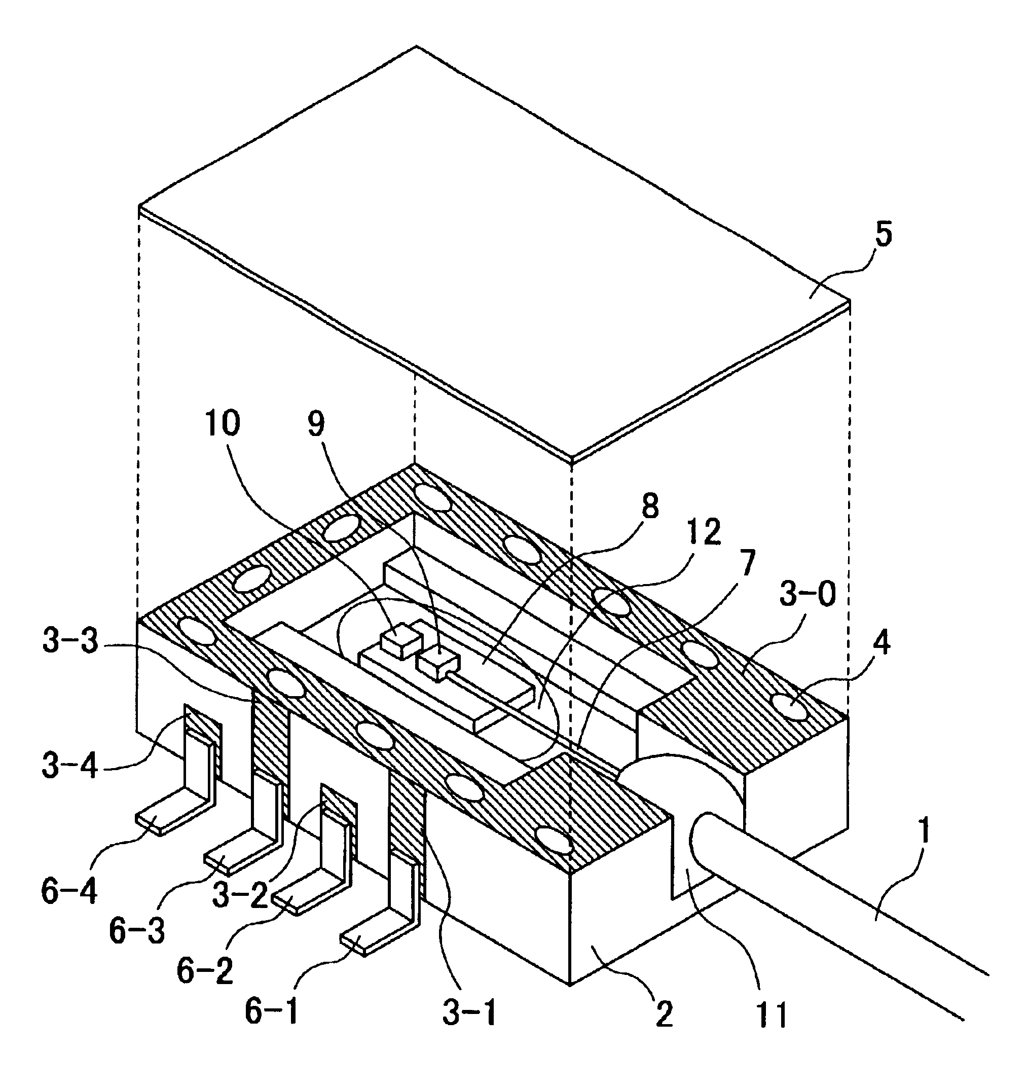
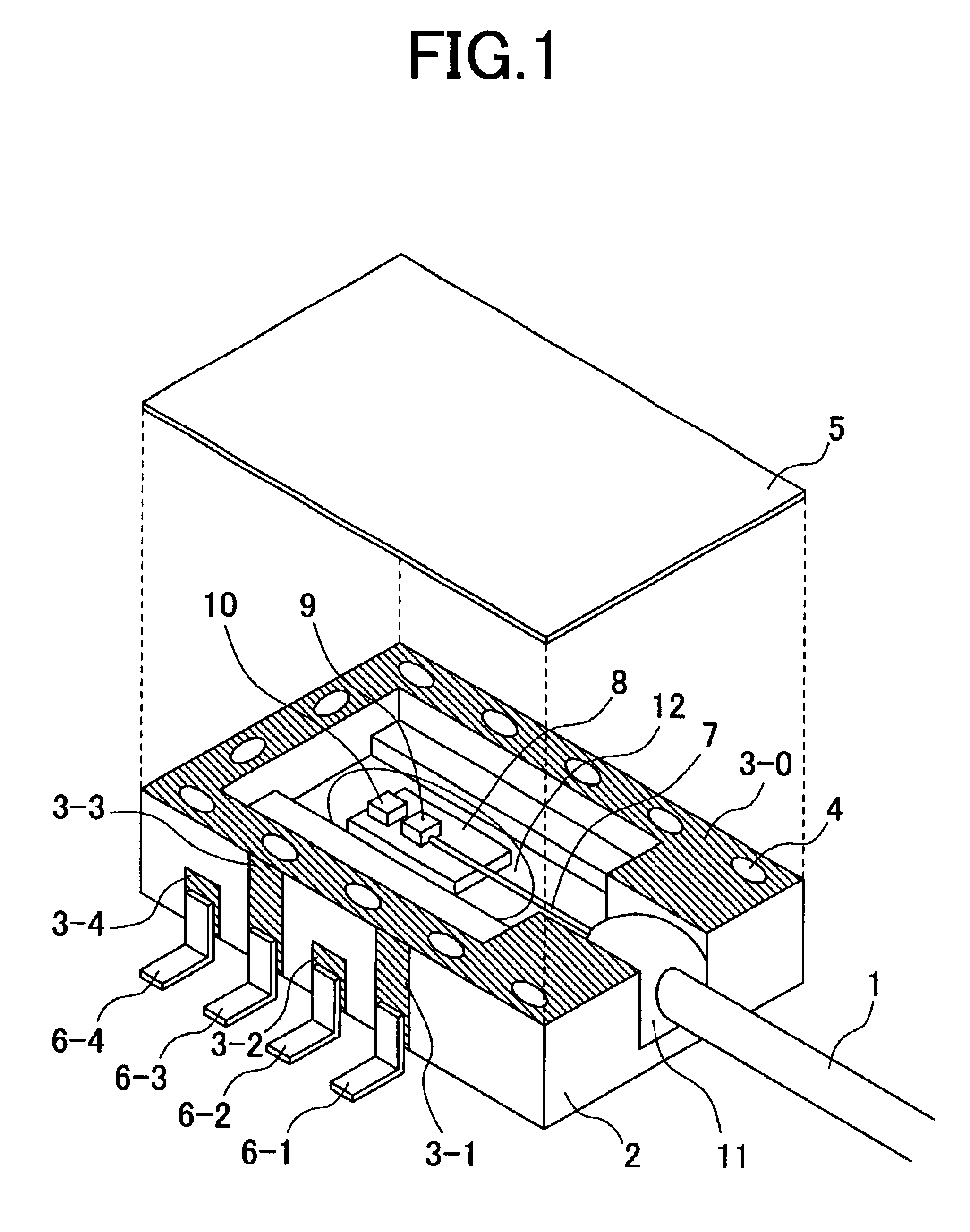
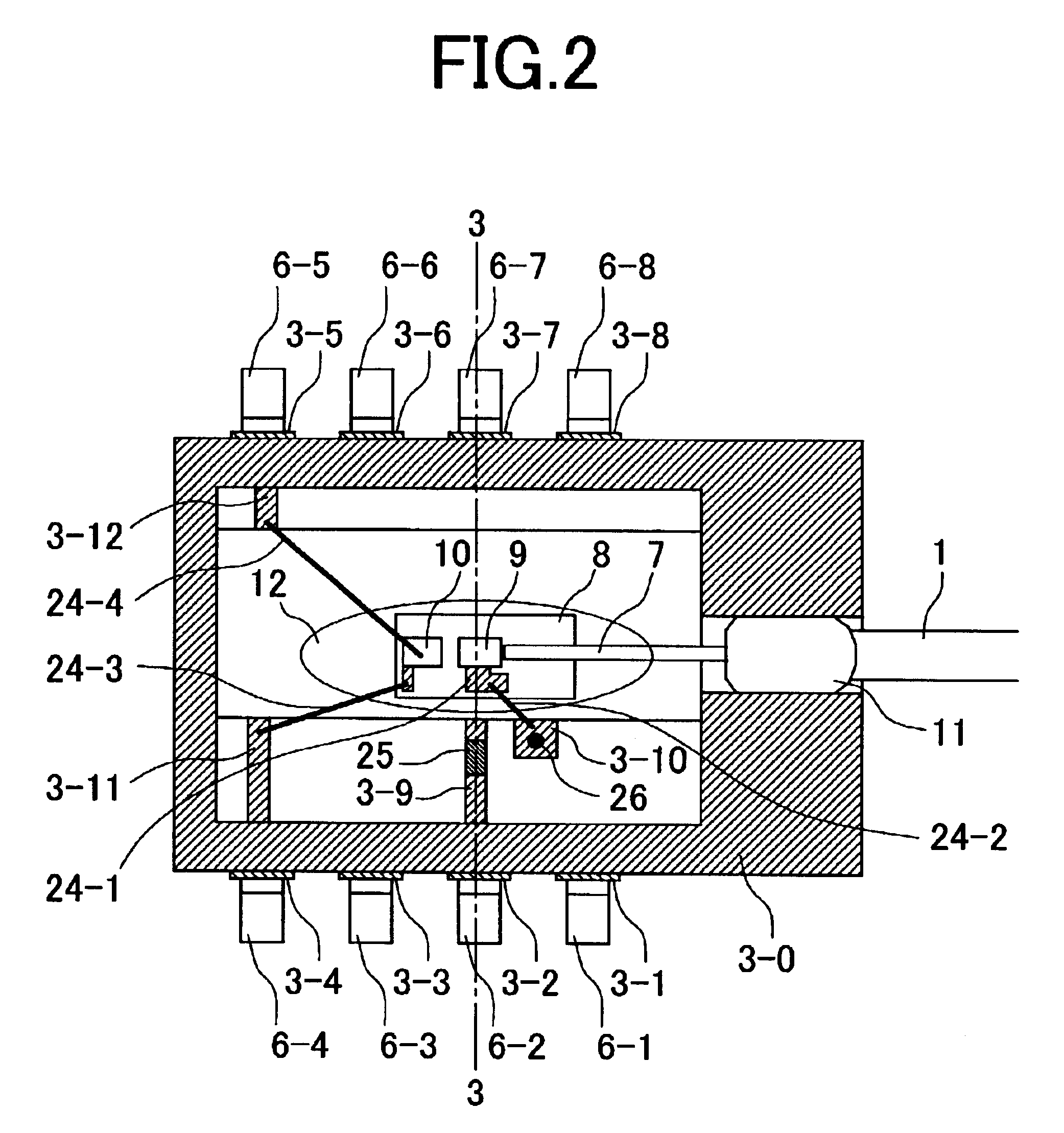
FIG. 1 is a perspective view of a LD module with a fiber pigtail according to the first embodiment of the present invention. In order to describe the inside of the LD module, and a method for bonding a cap, a cap 5 is shifted to a position above the LD module for the sake of illustration. Here, a part of details on an internal electrode pattern, a wire bond, and the like, are omitted. FIG. 2 is a plan view illustrating a state before the cap of the LD module shown in FIG. 1 is mounted. In FIG. 2, the electrode patterns, the wire bonds, and the like, inside the module are also illustrated in detail. FIG. 3 is a cross section of the LD module taking along line 3--3 in FIG. 2. A main body of the ceramic package is formed of three ceramic lamination layers. FIGS. 4 to 7 illustrate respective electrode patterns of three ceramic plate layers, which constitute the main...

second embodiment

A second embodiment is an optical module having a PD element and an IC element which amplifies output of the PD element.

FIG. 8 is a perspective view of a PD module with a fiber pigtail according to the second embodiment of the present invention. In order to describe the inside of the PD module, and a method for bonding a cap, the cap 5 is shifted to a position above the PD module for the sake of illustration. Here, a part of details on an electrode pattern, wire bonds, and the like, inside the package are omitted. FIG. 9 is a plan view of the PD module in FIG. 8, illustrating a state before the cap of the PD module is mounted. In FIG. 9, the electrode pattern, the wire bonds, and the like, inside the package are also illustrated in detail. FIG. 10 is a cross section of the PD module taken along line 10--10. in FIG. 9. FIGS. 11 to 14 illustrate respective electrode patterns of three ceramic plate layers, which constitute a ceramic package main body 4 of the PD module. FIG. 11 illustr...

third embodiment

A third embodiment is an optical module having the following: a LD element; a PD element that monitors output of the LD element; and an optical connector. Therefore, unlike the first and second embodiments, the present embodiment additionally includes an optical connector mechanism.

FIG. 15 is a perspective view of a LD module with an optical connector according to the third embodiment of the present invention. In order to describe the inside of the module, and a method for bonding a cap 5, the cap 5 and a connector fixing bracket 74 are shifted to a position above the module for the sake of illustration. Here, although this module has the same function as that of the LD module of the first embodiment, it has, for example, the following differences:

(1) An optical output interface is an optical connector, and has a connector mechanism.

(2) Leads are taken out from the bottom of a package.

In order to realize an optical connector mechanism, a ferrule 71 having a short bare fiber 7 is fix...


PUM


Abstract

An object of the disclosed technology is to realize, at low cost, an optical communication module capable of high-speed operation and having an excellent EMC property. A means for achieving the object is as follows. A main body of an optical module is formed of a ceramic multilayer structure, and a high-frequency line is provided. A surface of the main body is provided with an electrode pattern, which is electrically connected to a ground pin. A metal cap is secured to the electrode pattern using a conductive adhesive.

Description

BACKGROUND OF THE INVENTIONThe present invention relates to an optical module that is useful for a communication system using an optical fiber. To be more specific, the present invention relates to an optical module that has an optical fiber, or an optical connector, for inputting or outputting a light signal, and a terminal for inputting or outputting an electric signal, and that has a light-emitting device or a detector inside the optical module. In particular, a package main body is formed of a ceramic plate multi-layer structure, and the present invention is useful for an optical nodule which is intended for ultrahigh-speed operation at 10 Gbit / s or more.In recent years, the speed of optical communication systems is rapidly becoming faster, and prices thereof are also rapidly becoming lower. As a result, a faster optical module, a price of which is lower, is strongly demanded. As a package of the optical module, a plastic package, a metal package, a ceramic package, and the like...

Claims


Application Information

Patent Timeline
Patent Type & Authority Patents(United States)
IPC IPC(8): G02B6/42H01S5/022
CPCG02B6/421G02B6/4277G02B6/4239G02B6/4246G02B6/4248G02B6/4251G02B6/4285G02B6/4265G02B6/4286G02B6/4274
Inventor IDO, TATEMIYOSHIDA, KOUJI
Owner OCLARO JAPAN INC
Why Eureka
Try Eureka