Rolling bearing and spindle apparatus for machine tool

a technology of rolling bearings and spindles, which is applied in the direction of rolling contact bearings, shafts and bearings, rotary bearings, etc., can solve the problems of lubricant defect of guided surface, negative inner clearance of bearings, and increased roller load

Inactive Publication Date: 2004-06-01
NSK LTD
View PDF29 Cites 42 Cited by
  • Summary
  • Abstract
  • Description
  • Claims
  • Application Information

AI Technical Summary

Problems solved by technology

In case that the bearing rotates at a high speed at the operating time of the machine tool, grease filled inside the bearing or lubricating oil supplied by oil-air lubrication is scattered to the outer ring side by centrifugal force, so that in case of the inner ring guide retainer, there is a possibility that lubricant defect of the guided surface causes seizure.
Further, at the time of the high-speed rotation, due to expansion of the inner ring groove and outer cylinder cooling by the centrifugal force, and the increase of the inner / outer ring temperature difference by the influence of a motor built in a machine, the inner clearance of the bearing becomes negative during running, so that there is also a problem that roller load increases.
Further, the retainer is whirled by the centrifugal force at the time of the high-speed rotation, and the retainer made of the synthetic resin has also a problem that the amount of deformation is large in case that the strength of the retainer is low.
Particularly, in case of the roller guide retainer, since the retainer holds the rollers therein and is guided by the rollers, when whirling of the retainer is produced by the influence of the centrifugal force or when the amount of deformation is large, the roller is restrained in the pocket portion, and its operation is obstructed.
Further, the excessive load is applied onto the retainer by the rollers, so that there is fear that the retainer is broken.
At this time, there was a possibility that wear powders produced in the raceway surface and the guided surface 34a deteriorate the grease.
Therefore, lubricating property between the guided surface of the retainer and the guide surface of the inner ring remarkably lowers, which causes early breakage of the retainer and the inner ring.
However, the burr removal working is complicated, which causes the increase of cost of the rolling bearing.
In case that the bearing is used in the spindle apparatus for machine tool, if this FC run-out is produced, there is a possibility that an influence may be given on a problem of worsening the external appearance of the machine surface (problem of generating a sink mark).
In case that it is 30 wt % or more, the molding property is deteriorated and the external appearance is also bad.
However, in case of the cylindrical roller bearing, if the axial width of the retainer of the outer ring guide type is set so as to satisfy the above expression (1), there is a fear that a lead-in portion of the outer ring raceway surface, which is provided in order to smoothly perform the incorporation of the cylindrical rollers, interferes with the guided surface of the retainer by the axial movement of the inner ring due to an incorporation error and shaft expansion during running.
Hereby, such a disadvantage is caused that the brake is applied on running of the retainer and the guided surface of the retainer wears.
Namely, during running of the rolling bearing, the bad operation due to wear of the parting line and the torque change is not caused.

Method used


Image

  • Rolling bearing and spindle apparatus for machine tool
  • Rolling bearing and spindle apparatus for machine tool
  • Rolling bearing and spindle apparatus for machine tool

Examples


first embodiment

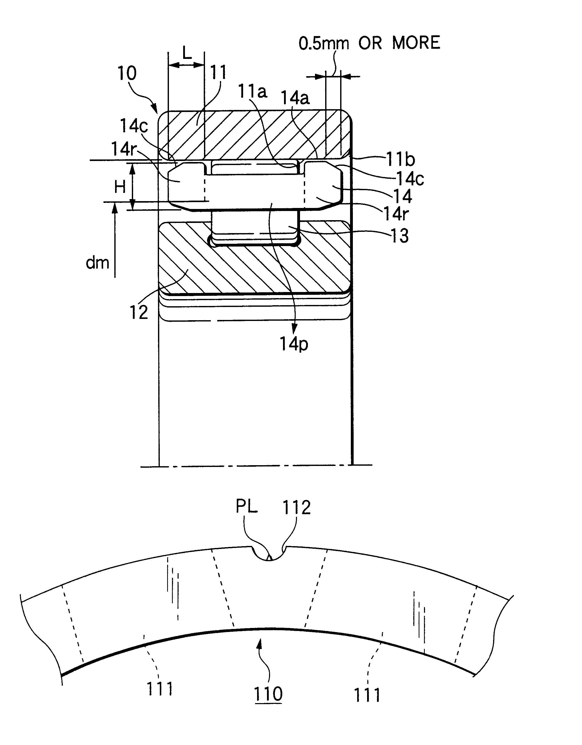
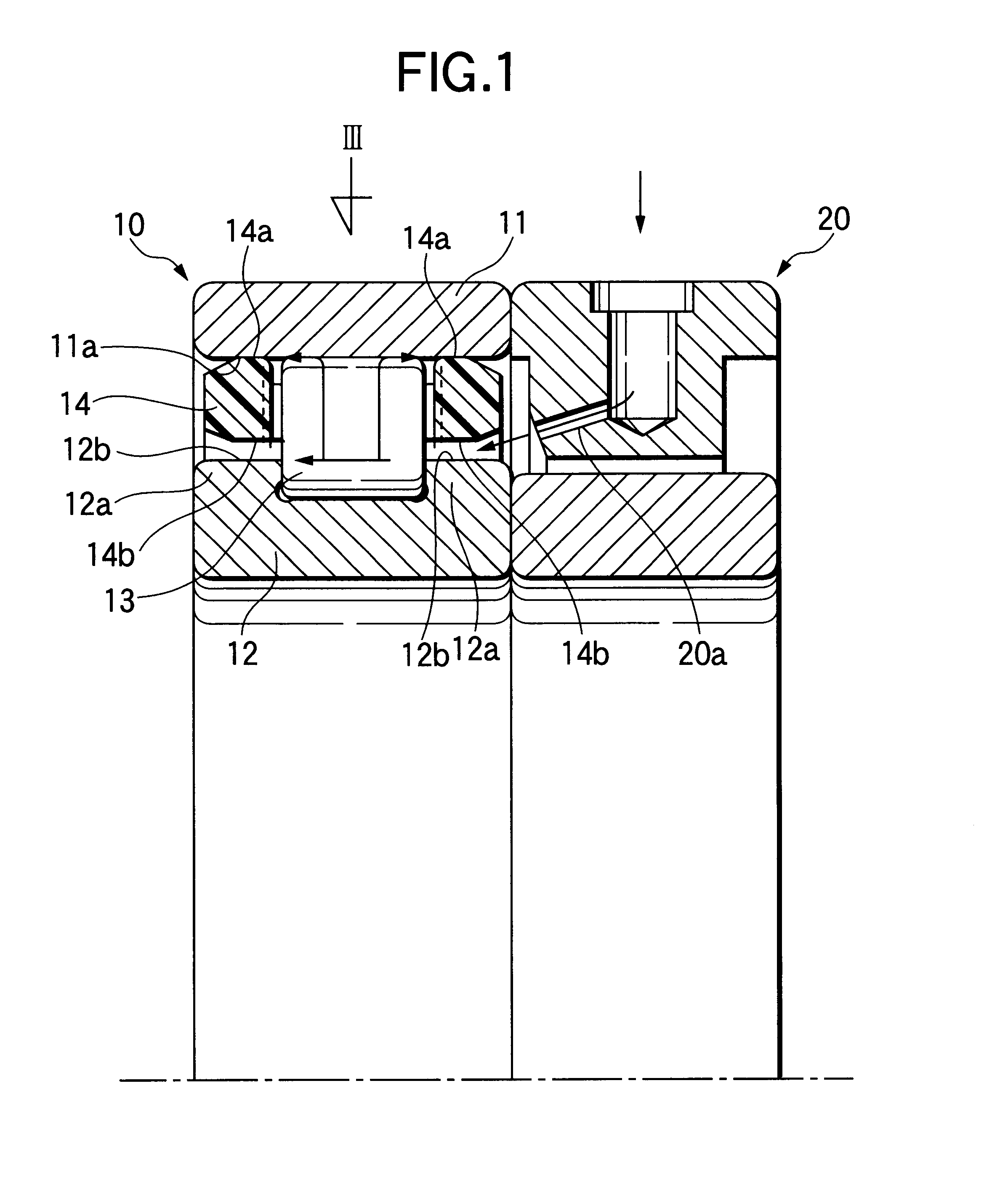
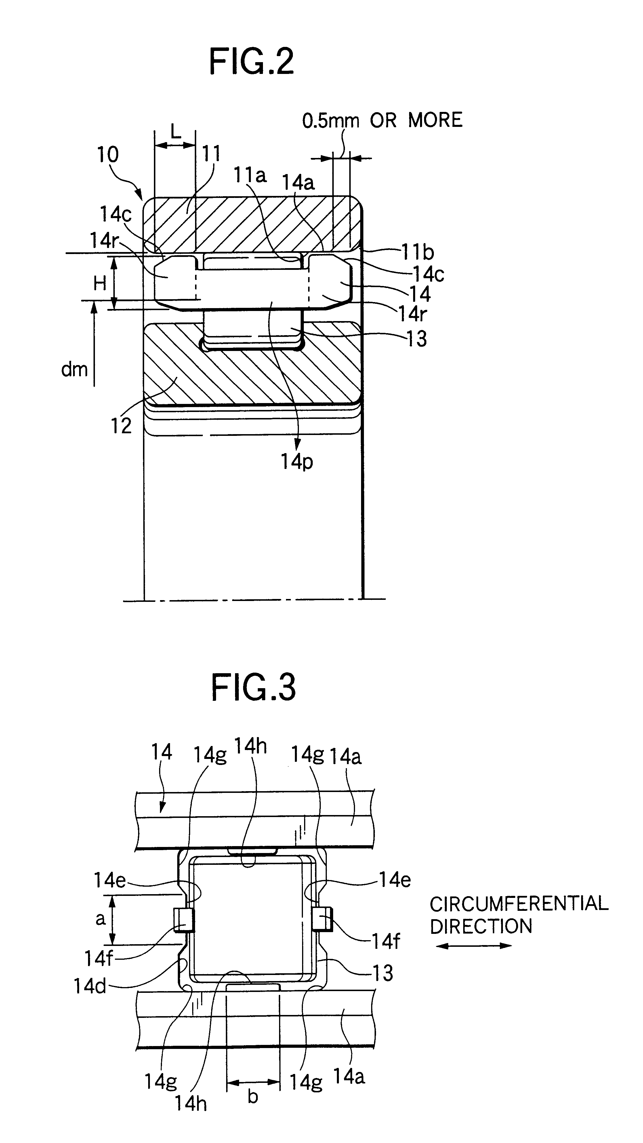
FIG. 1 is an axially sectional view, showing a rolling bearing according to the invention. FIG. 2 is an enlarged view showing only the rolling bearing in this embodiment. A rolling bearing 10 includes an outer ring 11 without rib, an inner ring 12 with ribs 12a at both ends, plural rollers (rolling elements) 13 rotatably provided between the both rings 11 and 12, and a retainer 14 for retaining the rollers 13. In FIG. 1, a lubricating oil supplying apparatus 20 for oil-air or oil-mist lubrication is provided adjacent to the rolling bearing 10. A supply passage 20a of the lubricating oil supplying apparatus 20 is directed to the inside of the rolling bearing 10 so as to eject the lubricating oil sent from the external with pressure, into the inside of the bearing 10.

The retainer 14 is positioned with respect to the inner periphery of the outer ring 11, and an outer surface 14a of the retainer 14 opposed to a raceway surface 11a of the outer ring 11 serves as a guided surface of the r...

second embodiment

FIG. 7 is a sectional view of a cylindrical roller bearing according to the invention, which is similar to the sectional view in FIG. 2. In FIG. 7, a bearing 30 has an outer ring 31 without rib, an inner ring 32 with ribs 32a at both ends, plural rollers (rolling elements) 33 rotatably provided between the both rings 31 and 32, and a retainer 34 for retaining the rollers 33. A lubricating oil supplying apparatus for oil-air or oil-mist lubrication (not shown in FIG. 7) is provided adjacent to the roller bearing 30.

Similarly to the embodiment shown in FIG. 2, the retainer 34 is also positioned with respect to the inner periphery of the outer ring 31. However, in this embodiment, a guided surface of the retainer 34 is provided on only an outer surface 34a of an annular portion 34r on the right side in FIG. 7, opposed to a raceway surface 31a of the outer ring 31. In this embodiment, H is a radial length of a section of the right annular portion 34r of the retainer 34, and L is an axia...

third embodiment

FIG. 8 is a sectional view of a cylindrical roller bearing according to the invention, which is similar to the sectional view in FIG. 2. In FIG. 8, a bearing 40 has an outer ring 41 with ribs, an inner ring 42, plural rollers (rolling elements) 43 rotatably provided between the both rings 41 and 42, and a retainer 44 for retaining the rollers 43. A lubricating oil supplying apparatus for oil-air or oil-mist lubrication (not shown in FIG. 8) is provided adjacent to the rolling bearing 40.

Similarly to the embodiment shown in FIG. 2, the retainer 44 is also positioned with respect to the inner periphery of the outer ring 41, and a guided surface of the retainer 44 is provided on a retainer outer surface 44a opposed to a raceway surface 41a of the outer ring 41. The basic constitution except that the inner ring 42 has no ribs is the same as that in the above-described embodiment, and the working and the effect can be obtained similarly.


PUM

PropertyMeasurementUnit
depthaaaaaaaaaa
chamfering angleaaaaaaaaaa
outer diameteraaaaaaaaaa

Abstract

A rolling bearing includes an inner ring having an outer surface, an outer ring having an inner surface, a plurality of rolling elements rotatably disposed between the inner ring and the outer ring, and a retainer for retaining the rolling elements. The retainer is made of a resin material and is positioned with respect to the inner surface of the outer ring or the outer surface of the inner ring. The retainer includes a pair of annular portions axially arranged in parallel and a columnar portion coupling the annular portions. Then, the rolling bearing satisfies the following expression: AI=LH<3> / dm>=0.025 in which H is a radial length of a section of the annular portion, L is an axial length of the same, and dm is PCD of the rolling element.

Description

1. Field of the InventionThe present invention relates to a rolling bearing for supporting a spindle shaft of a machine tool that rotates at a high speed, and a spindle apparatus for machine tool using the rolling bearing.2. Description of the Related ArtThe conventional art will be described with a cylindrical roller bearing as an example. A bearing for supporting a spindle shaft of a machine tool requires high rotational accuracy and rigidity in order to keep the machining accuracy high. The cylindrical roller bearing used for this purpose is usually used with an inner clearance of the bearing adjusted to a small clearance of about 5 .mu.m after the roller bearing was incorporated into the spindle shaft and a housing.On the other hand, there is a recent tendency to use the spindle apparatus at a high speed in order to improve the machining efficiency, and it is necessary for the bearing to correspond to the speed-up. As a bearing capable of corresponding to this request, a cylindr...

Claims


Application Information

Patent Timeline
Patent Type & Authority Patents(United States)
IPC IPC(8): F16C33/46F16C33/38
CPCF16C33/3856F16C33/4635F16C33/467F16C33/6603F16C33/6662F16C33/3806F16C33/3887F16C33/4605F16C19/26F16C19/163F16C2322/39F16C2220/04F16C19/548
Inventor MATSUYAMA, NAOKISUGITA, SUMIOKOIWA, YUANZAI, TAKAAKIMISAWA, TAMOTSUTERASAKI, MASARU
Owner NSK LTD
Why Eureka
Try Eureka