One-mask metal-insulator-metal capacitor and method for forming same

a technology of metal-insulator and capacitor, which is applied in the direction of capacitor, semiconductor device details, semiconductor/solid-state device devices, etc., can solve the problems of defective capacitors, increased cost and complexity associated with the fabrication process, etc., and achieves the effect of reducing the number of mask steps and being convenient to us

Inactive Publication Date: 2004-06-15
INT BUSINESS MASCH CORP
View PDF14 Cites 13 Cited by
  • Summary
  • Abstract
  • Description
  • Claims
  • Application Information

AI Technical Summary

Benefits of technology

to provide a MIM capacitor that is not prone to leakage down the capacitor sidewall and a method for manufacturing the MIM capacitor that is inexpensive and efficient (e.g., by reducing the number of mask steps required for fabrication of the capacitor structure).
This capacitor structure may be formed by depositing a metal-insulator-metal capacitor stack on top of a via, masking and etching an upper electrode of the metal-insulator-metal capacitor stack, depositing and etching a first spacer on an edge surface of the upper electrode, defining a lower electrode of the metal-insulator-metal capacitor based on the first spacer, depositing and etching a second spacer on a surface of the first spacer and an edge of the lower electrode, and forming a wiring layer on a surface of the upper electrode and a surface of the second spacer. This capacitor structure and its corresponding method of manufacture provide a protected capacitor structure that is fabricated with increased efficiency (e.g., fewer mask steps).
FIG. 2 is a conventional MIM capacitor that avoids a leakage problem and involves three additional mask layers;
FIG. 3 is a conventional MIM capacitor that avoids a leakage problem and involves two additional mask layers;

Problems solved by technology

One basic problem with MIM capacitors is that if the sidewalls are vertical, then there is a potential for a leakage path down the capacitor sidewalls, which results in defective capacitors. FIG. 1 provides an example of a MIM capacitor prone to leakage down the capacitor sidewalls and shows a convential capacitor structure including an upper electrode 102, a dielectric layer 103, and a lower electrode 104, a via 107, a via 140, metal layer 170, a via 172, a via 174, metal layer 176, intermetal dielectric 106 and metal layer 160.
Although this configuration addresses the problem of leakage down the capacitor sidewalls, the additional mask layer leads to an increased cost and complexity associated with the fabrication process.

Method used


Image

  • One-mask metal-insulator-metal capacitor and method for forming same
  • One-mask metal-insulator-metal capacitor and method for forming same
  • One-mask metal-insulator-metal capacitor and method for forming same

Examples


Embodiment Construction

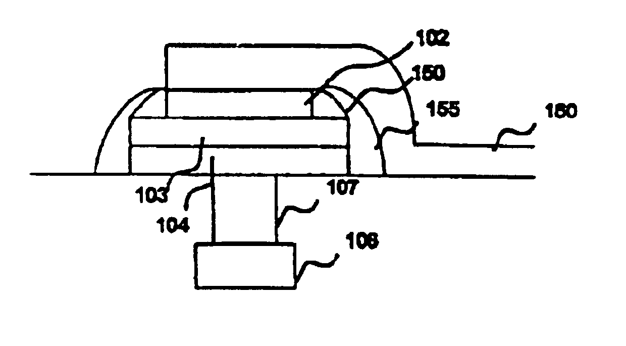
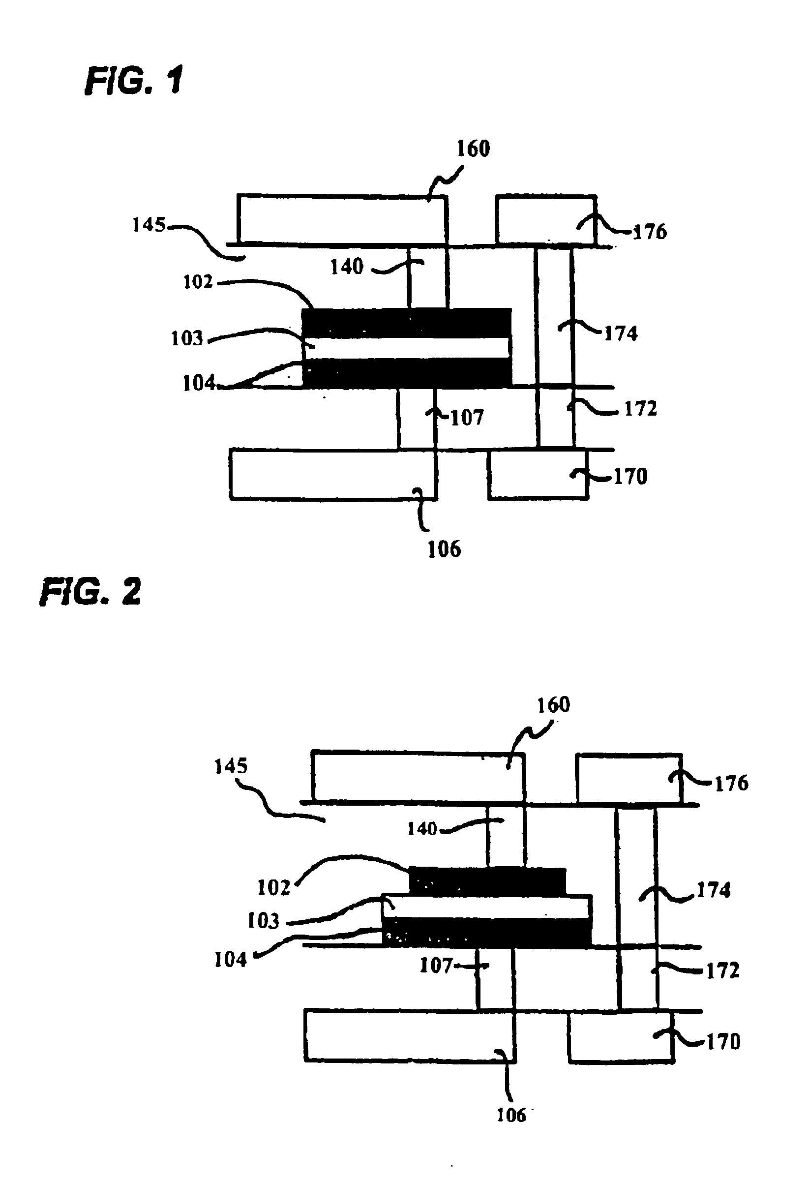
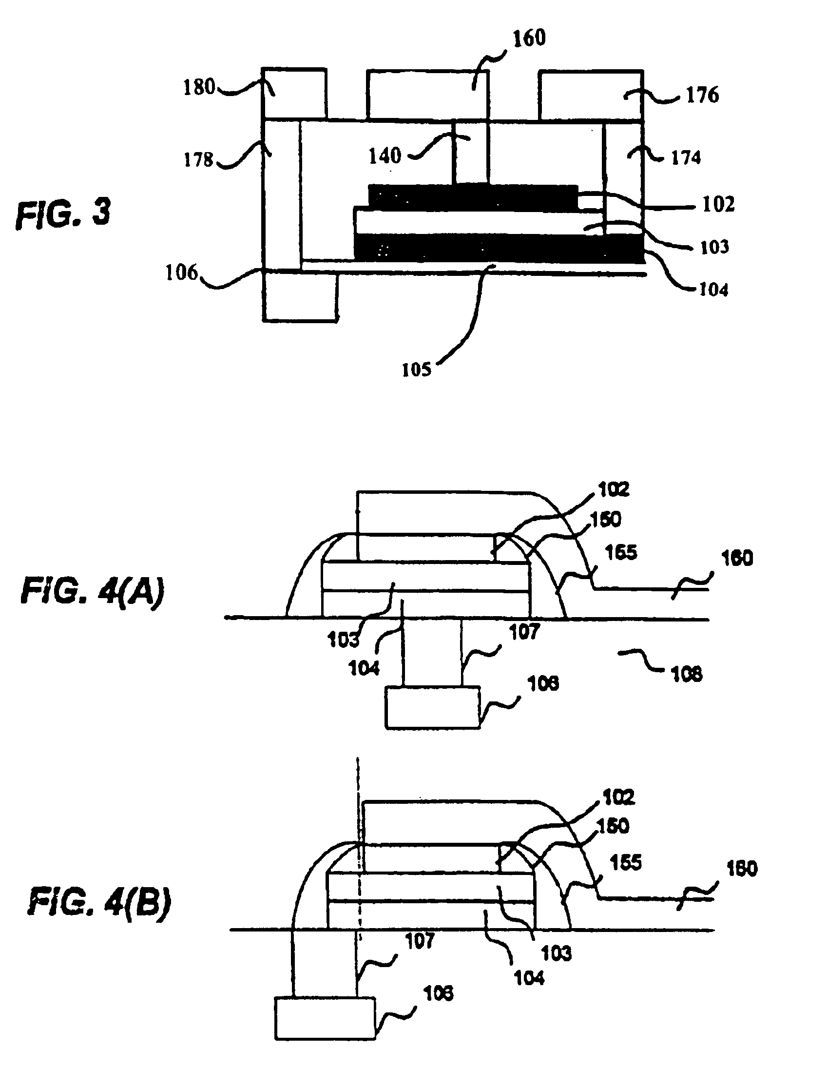
Referring now to the drawings, FIG. 4(A) depicts a MIM capacitor 400 in accordance with the present invention. MIM capacitor 400 includes an insulation layer 108, a capacitor stack 102, 103, 104, a via 107, and a metal layer 106. In a preferred embodiment, via 107 may be formed of any suitable via material including tungsten and metal layer 106 may comprise any suitable conductive material including copper.

The capacitor stack includes a lower electrode 104 formed on a surface of the insulation layer 108, a dielectric layer 103 formed on a surface of the lower electrode 104, and an upper electrode 102 formed on a surface of the dielectric layer 103. The upper electrode 102 and lower electrode 104 may be formed on any suitable conductive material, including tungsten.

MIM capacitor 400 additionally includes a first spacer 150 and a second spacer 155. The first spacer 150 is formed on a side portion of the upper electrode 102. In a preferred embodiment, the first spacer provides a comple...


PUM


Abstract

A capacitor structure formed on an insulation layer includes a lower electrode formed on a surface of the insulation layer, a dielectric layer formed on a surface of the lower electrode, an upper electrode formed on a surface of the dielectric layer, a first spacer formed on a side portion of the upper electrode, and a second spacer formed on a side portion of the first spacer and a side portion of the lower electrode. This capacitor structure is formed by depositing a metal-insulator-metal capacitor stack on top of a via, masking and etching an upper electrode of the metal-insulator-metal capacitor stack, depositing and etching a first spacer on an edge surface of the upper electrode, defining a lower electrode of the metal-insulator-metal capacitor based on the first spacer, depositing and etching a second spacer on a surface of the first spacer and an edge of the lower electrode, and forming a wiring layer on a surface of the upper electrode and a surface of the second spacer. This capacitor structure provides a capacitor that is not prone to leakage down the capacitor sidewall and the corresponding method of manufacture provides a capacitor that is fabricated with increased efficiency (e.g., fewer mask steps).

Description

1. Field of the InventionThe present invention generally relates to a metal-insulator-metal (MIM) capacitor having a first spacer protecting an upper electrode and a second spacer protecting a lower electrode, and a method of manufacturing the same.2. Description of the Related ArtBack of the line capacitors fabricated as part of the wire and via process are a required part of integrated circuit manufacturing. MIM capacitors have been in high volume manufacturing for several years and, for the foundry technologies, will see increasing use in the future. One basic problem with MIM capacitors is that if the sidewalls are vertical, then there is a potential for a leakage path down the capacitor sidewalls, which results in defective capacitors. FIG. 1 provides an example of a MIM capacitor prone to leakage down the capacitor sidewalls and shows a convential capacitor structure including an upper electrode 102, a dielectric layer 103, and a lower electrode 104, a via 107, a via 140, meta...

Claims


Application Information

Patent Timeline
Patent Type & Authority Patents(United States)
IPC IPC(8): H01L21/02H01L23/52H01L23/522
CPCH01L23/5223H01L28/55Y10S438/957H01L2924/0002H01L2924/00
Inventor ADLER, ERICSTAMPER, ANTHONY KENDALL
Owner INT BUSINESS MASCH CORP
Why Eureka
Try Eureka