
High-speed, hand-held reciprocating method for cutting, carving, sawing, chiseling, filing, sanding, and engraving

a reciprocating method and high-speed technology, applied in the field of hand-held tools, can solve the problems of tool being pulled in an unwanted direction, affecting the work efficiency of the tool, and affecting the quality of the tool, etc., and achieves the effects of convenient holding and manipulation, precise work, and comfortable us

Inactive Publication Date: 2004-06-22
JONES WILLIAM RANDOLPH
View PDF18 Cites 82 Cited by
  • Summary
  • Abstract
  • Description
  • Claims
  • Application Information

AI Technical Summary

Benefits of technology

"The invention is a hand-held, reciprocating attachment for cutting, carving, sawing, chiseling, filing, sanding, and engraving various materials with various cutting tools. The attachment is versatile, compact, easy-to-use, reliable, economical, and can be used with existing power rotary tools without the need for additional components. It can accommodate various types of small cutting tools and allows for deep, perpendicular cuts and in cramped spaces. The attachment has a minimum number of pieces, is economical and reliable, and is designed to be quickly and easily attached to a rotary power source. It also has a high-speed capability, is easy to assemble and use, and allows for the use of miniature chisels. The attachment can be made in different sizes, shapes, and materials, and can be secured to a power rotary source using different methods. Overall, the hand-held, reciprocating attachment provides a flexible, efficient, and economical solution for various cutting and engraving needs."

Problems solved by technology

Such tools currently available exhibit problems in regards to delicate, detail work.
Although such rotary tools are very useful in numerous applications they do have limitations.
When trying to perform detailed shaping or precise removal of material from a work piece with a hand-held rotating tool, a ball grinder, sanding disc or drum, or cutting wheel attachment can grab a material and cause a tool to be pulled in an unwanted direction thereby blemishing or even destroying a work piece.
For one example of a professional application, this potentially damaging scenario is a real concern when modifying or repairing very expensive electronic printed circuit board assemblies.
When the operator loses control of a rotary cutting tool due to grabbing numerous unwanted clad traces can be severed, sometimes in an un-repairable area of the board, resulting in hundreds or thousands of dollars in wasted inventory.
Also, using a manual hobby razor knife in such as application requires quite a bit of force that can promote slipping and loss of control.
Cutting with a rotary tool is limited to the use of a spinning, abrasive cutting wheel, and gaining access to a desired area of a work piece at a desired cutting angle is sometimes impossible to achieve.
This is because rotary cutting tools have a limitation in that some of the parts comprising the drive mechanism of the cutting wheel are either above, below, to the right, or to the left of the plane of the cutting wheel depending on orientation.
Carving with a hand-held rotary tool requires the use of a spinning, course-cutting attachment that, too, can catch on a material, cause a tool to be pulled in an unwanted direction, and cause damage to a work piece.
Sawing with a hand-held rotary tool is limited to the use of a spinning, abrasive cutting wheel, or a round saw with teeth, and gaining access to a desired area of a work piece at a desired cutting angle is sometimes impossible to achieve.
Chiseling with a hand-held rotary tool using only rotating motion is potentially dangerous because it requires a rotating bit containing cutting blades that is difficult to control and certainly not suited for fine, detail work.
Filing with a hand-held rotary tool is limited to a use of a spinning, abrasive cutting wheel or a spinning abrasive bit.
Gaining access to a desired area of a work piece at a desired angle with an abrasive wheel for filing is sometimes impossible to achieve, and filing with a spinning abrasive bit can cause unwanted variable-depth cuts, or unwanted grooves, in a work surface.
Sanding with a hand-held rotary tool requires a spinning sanding disc or a sanding drum attachment that can grab a material, cause a tool to be pulled in an unwanted direction, and either cause damage to or destroy a work piece.
Some available hand-held reciprocating tools are too large and too heavy to hold properly for extreme detail work because they include an AC motor or a DC motor with batteries.
Also, they are more dedicated to certain applications, such as just sanding or just carving, and don't allow for an assortment of tool attachment types.
Some do not hold tool attachments firmly enough for extremely fine control of a tool attachment.
Reciprocating carving tools that don't activate until the cutting edge is pressed against the work piece with a force parallel to the longitudinal axis are not suited for knife blades, saw blades, files, and sanders because such tool attachments require pressure to be applied perpendicular to the tool's longitudinal axis.
Therefore, force-activated tools are typically limited to chisels and gouges and are not suited for delicate work because the required force to active may exceed the mechanical strength of the work piece.
Hammer-type reciprocating tools impart a potentially damaging impulse to delicate work pieces.
They do not allow for a fine degree of force control required for delicate work pieces.
Engravers are reciprocating tools, but they are limited in their ability to provide a variable-speed, variable-length stroke.
They also are not suited for the use of other types of cutting tools and are dedicated to engraving only.
The referenced inclined annular groove will result in large acceleration and deceleration forces between the annular groove and the ball and socket set screw.
Furthermore, a spring's response limited the attainable reciprocating frequency.
Furthermore, the saw blade is attached with screws that are subject to loosening under vibration and the saw blade mounting method requires that either special, non-standard saw blades be purchased by the consumer or requires that the consumer modify existing saw blades for adequate mounting.
The elliptical orbit will result in large acceleration and deceleration forces between the cam groove and the cam key resulting in excessive wear.
A variable angle reciprocating tool in U.S. Pat. No. 5,832,611 to Schmitz, Nov. 10, 1998, claimed a motor housing and motor and is bulky and heavy, which is a negative in regards to fine detail work.
A low vibration motion translation system in U.S. Pat. No. 6,012,346 to Vo, Jan. 11, 2000, claims a low vibration motion translation system but it neither provides a detailed solution for affixing an outside housing, which would thereby make a hand-held device for an end user, nor does it provide detailed solutions for easily affixing various tools to the reciprocating piece.
It utilizes a spring in its design and therefore its frequency response is limited.
Furthermore, its hammer-type action could impart a potentially damaging impulse to delicate work pieces
A variable angle reciprocating tool in U.S. Pat. No. 6,138,364 to Schmitz, Oct. 31, 2000, employed multiple gears and multiple bearings which make the assembly more complex and therefore more prone to mechanical problems.
Furthermore, I am very familiar with both the hobby industry and the tool industry and have never seen anything like my hand-held, reciprocating attachment promoted for sale.
Rotary cutting wheels and rotary saw blades have a limitation in that the depth of any cut cannot exceed their radius due to the interfering axial drive.
No use of gears allows for improved wear by eliminating more wear surfaces and minimizing potential mechanical problems.
The need to place excessive pressure on a cutting edge for some applications is dangerous and can injure a user if the cutting edge slips, and can also be damaging to the work piece.
Also excessive pressure on a cutting edge can reduce accuracy.
Also, numerous strokes are quite often required, at the expense of time and energy, to cut through material or to remove a desired amount of material.
This leads to user fatigue and loss of accuracy.
A greater number of strokes, again, leads to user fatigue and loss of accuracy.

Method used


Image

  • High-speed, hand-held reciprocating method for cutting, carving, sawing, chiseling, filing, sanding, and engraving
  • High-speed, hand-held reciprocating method for cutting, carving, sawing, chiseling, filing, sanding, and engraving
  • High-speed, hand-held reciprocating method for cutting, carving, sawing, chiseling, filing, sanding, and engraving

Examples


Embodiment Construction

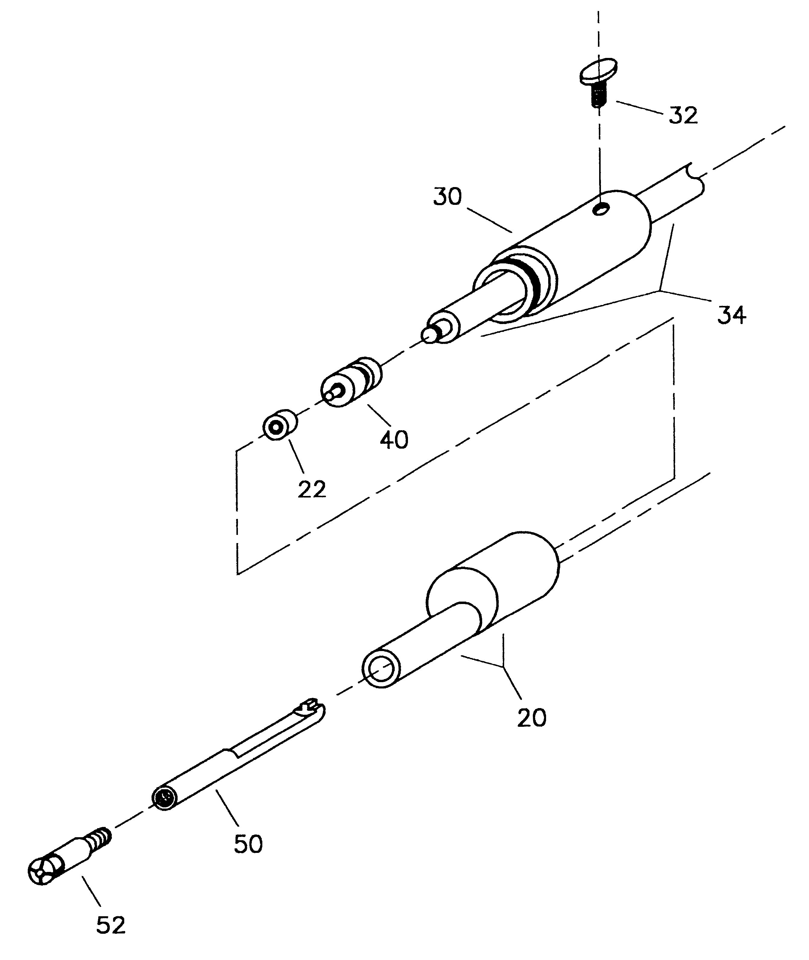
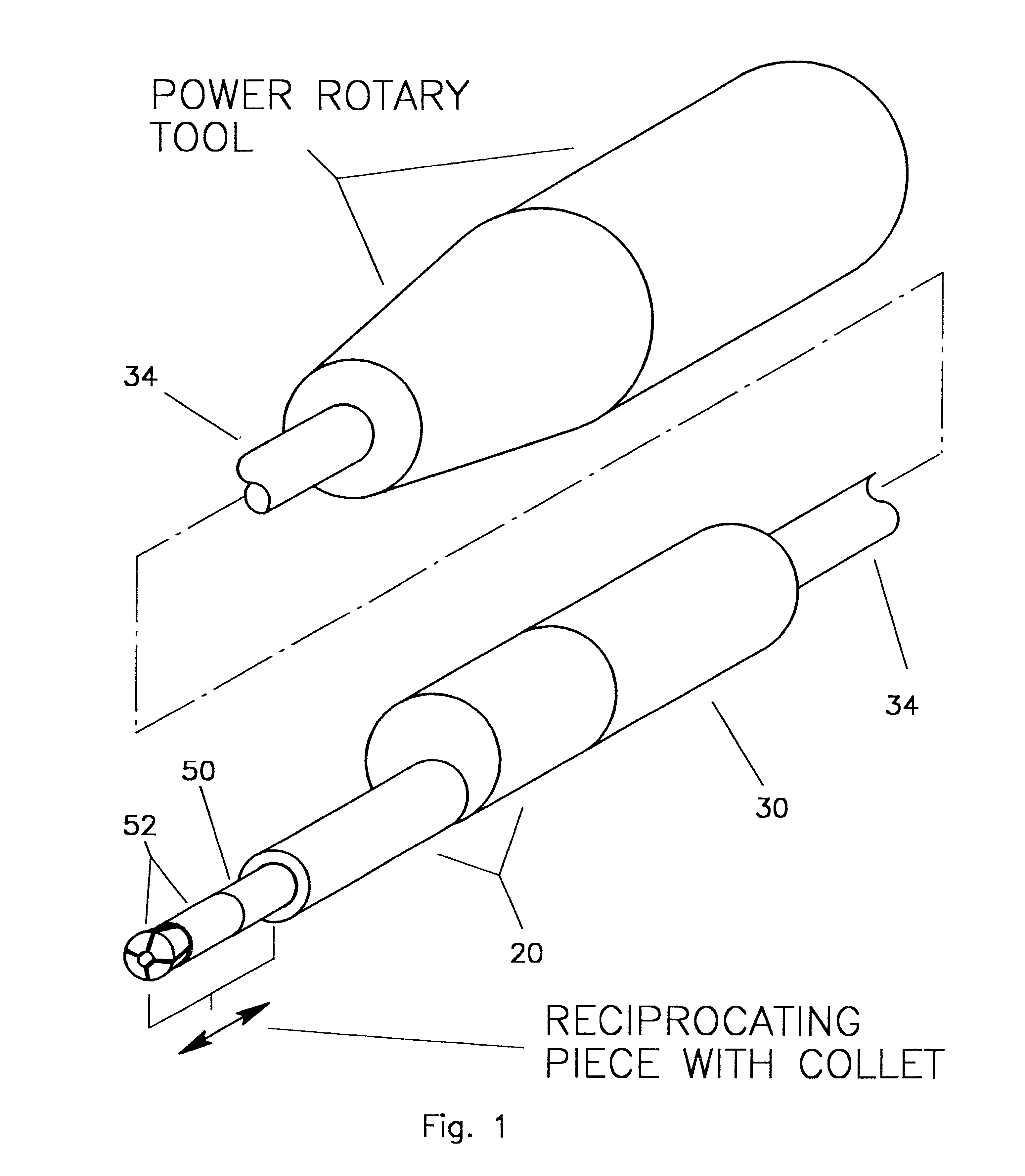
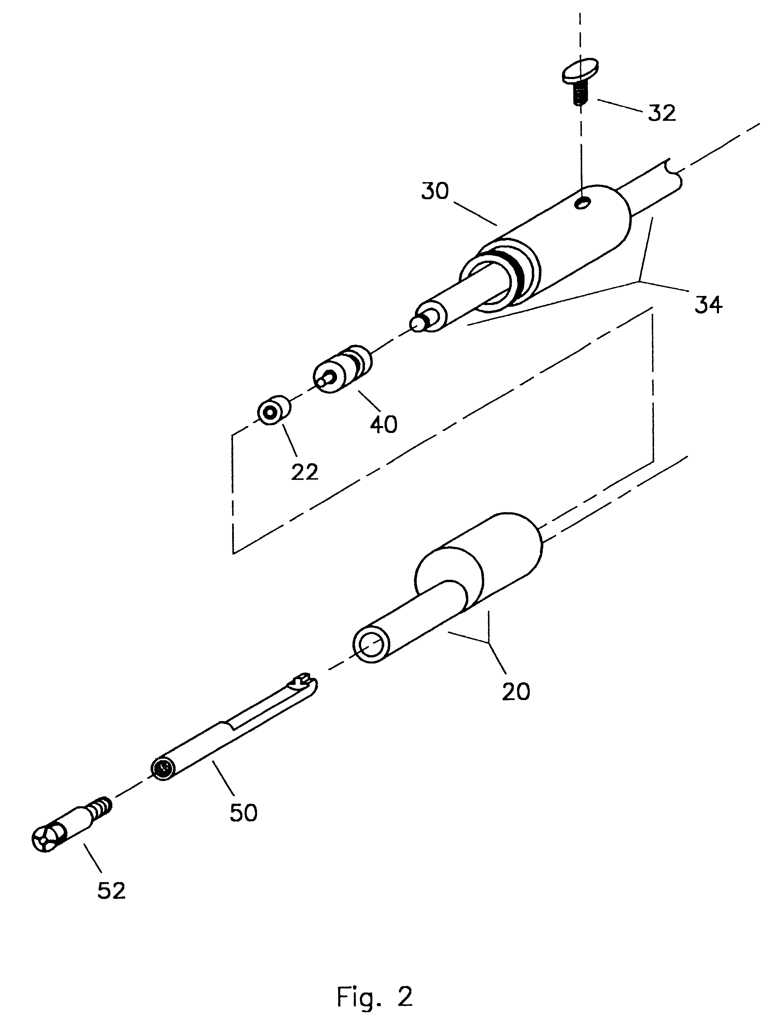
A high-speed, hand-held reciprocating method for cutting, carving, sawing, chiseling, filing, sanding, and engraving of the subject invention provides for greatly improved ease in cutting, carving, sawing, chiseling, filing, sanding, and engraving in a multitude of applications. A preferred embodiment is described herein but in no way is intended to limit design details, size, materials, finish, or methods of manufacturing, of the subject invention. FIG. 1 shows a perspective of the preferred embodiment. FIG. 2 shows an exploded view of the preferred embodiment. My hand-held, reciprocating attachment comprises one assembly that includes a machined, front one-piece enclosure 20, FIG. 3A and FIG. 3B, a machined, one-piece rear one-piece enclosure 30, FIG. 4A and FIG. 4B, a machined, one-piece rotatively driven rotating piece 40 with an integral cam groove, FIG. 5A and FIG. 5B, a machined, one-piece reciprocating piece 50 with an integral cam follower and an attachment point for a tool...


PUM

PropertyMeasurementUnit
lengthaaaaaaaaaa
diameteraaaaaaaaaa
widthaaaaaaaaaa

Abstract

A high-speed, hand-held attachment for flex rotor shafts of power rotary tools, and also for direct attachment to power rotary tools without flex rotor shafts, that converts rotary motion to reciprocating motion for precision control of cutting, carving, sawing, chiseling, filing, sanding, and engraving on delicate work pieces. The attachment is one assembly comprising a one-piece front one-piece enclosure (20), a rear one-piece enclosure (30), a high-speed bearing (22), a one-piece rotating piece (40) with integral cam groove, a one-piece reciprocating piece (50) with an integral cam follower on one end and with its other, exposed end accomodating the attachment of a chuck or collet and with geometry to prevent rotation, and a thumbscrew (32). Rotating piece (40) attaches directly to the rotary power source and provides the cam action drive to reciprocating piece (50). Bearing (22) provides rotative support for the other end of rotating piece (40). Reciprocating piece (50) slidably mounts in front one-piece enclosure (20). Front one-piece enclosure (20) and rear one-piece enclosure (30) are attached to each other and maintain proper alignment for rotating piece (40), bearing (22), and reciprocating piece (50). Thumbscrew (32) secures the attachment to the flex rotor shaft of a power rotary tool. A tool holder / collet is attached to the exposed end of reciprocating piece (50) whereby numerous types of cutting tools may be utilized. Alternative versions of the rear one-piece enclosure, (30A) and (30B), described herein, allow for attachment directly to power rotary tools without flex rotor shafts. Alternative versions of the reciprocating piece, (50A), (50B), and (50C), and of the rotating piece, (40A), are also described herein.

Description

1. Field of InventionThis present invention relates to hand-held tools, specifically to a hand-held reciprocating attachment for power rotary tools.2. Discussion of Prior ArtPower-driven hand-held rotary tools and reciprocating tools are known to exist in prior art. Such tools currently available exhibit problems in regards to delicate, detail work.Rotary tools rotate tool attachments, such as ball grinders, sanding discs and drums, and cutting wheels, at a variable RPM up to very high RPM. Although such rotary tools are very useful in numerous applications they do have limitations. When trying to perform detailed shaping or precise removal of material from a work piece with a hand-held rotating tool, a ball grinder, sanding disc or drum, or cutting wheel attachment can grab a material and cause a tool to be pulled in an unwanted direction thereby blemishing or even destroying a work piece. For one example of a professional application, this potentially damaging scenario is a real c...

Claims


Application Information

Patent Timeline
Patent Type & Authority Patents(United States)
IPC IPC(8): B26D5/08B26D5/16
CPCB26D5/16Y10T279/17529Y10T83/04Y10T83/50Y10T83/9457Y10T83/9459
Inventor JONES, WILLIAM RANDOLPH
Owner JONES WILLIAM RANDOLPH
Learn More